El concreto prefabricado no es un material distinto: es una forma de construir en la que la estructura se arma con piezas que llegan hechas y se unen en obra. Su comportamiento sísmico depende menos de la sección de la columna que de lo que ocurre en la junta: un edificio bien detallado se comporta como un marco; uno mal conectado, como una pila de piezas apoyadas.
Cuando ese edificio se aísla en la base, el reparto de demandas cambia. La superestructura se mueve casi como cuerpo rígido, la deriva entre piso cae y muchas conexiones dejan de trabajar en el rango inelástico. Pero el cortante no desaparece: se transfiere completo en la interfaz de aislamiento, y el desplazamiento también se concentra ahí. La estructura es más sencilla de analizar y mucho más exigente en dos lugares: la conexión del aislador y la junta que lo rodea.
Qué cambia y qué no cuando el edificio se aísla
Con un periodo aislado del orden de dos a cuatro segundos, las aceleraciones de piso bajan y con ellas las fuerzas inerciales que llegan a las conexiones viga-columna, a los anclajes de fachada y al contenido. En un marco prefabricado, muchos nudos que en un edificio fijo se diseñan para fluencia pueden quedarse en el intervalo elástico.
Lo que no cambia es la lógica: el diafragma sigue teniendo que existir. Las fuerzas horizontales de cada nivel deben llegar hasta el plano de aislamiento, y para eso la losa necesita continuidad o conectores mecánicos. ACI 318-19, §16.2, exige que las conexiones entre elementos prefabricados resistan las fuerzas de diseño y absorban las tolerancias de montaje; las disposiciones de integridad estructural siguen aplicando.
El plano de aislamiento: la junta que manda
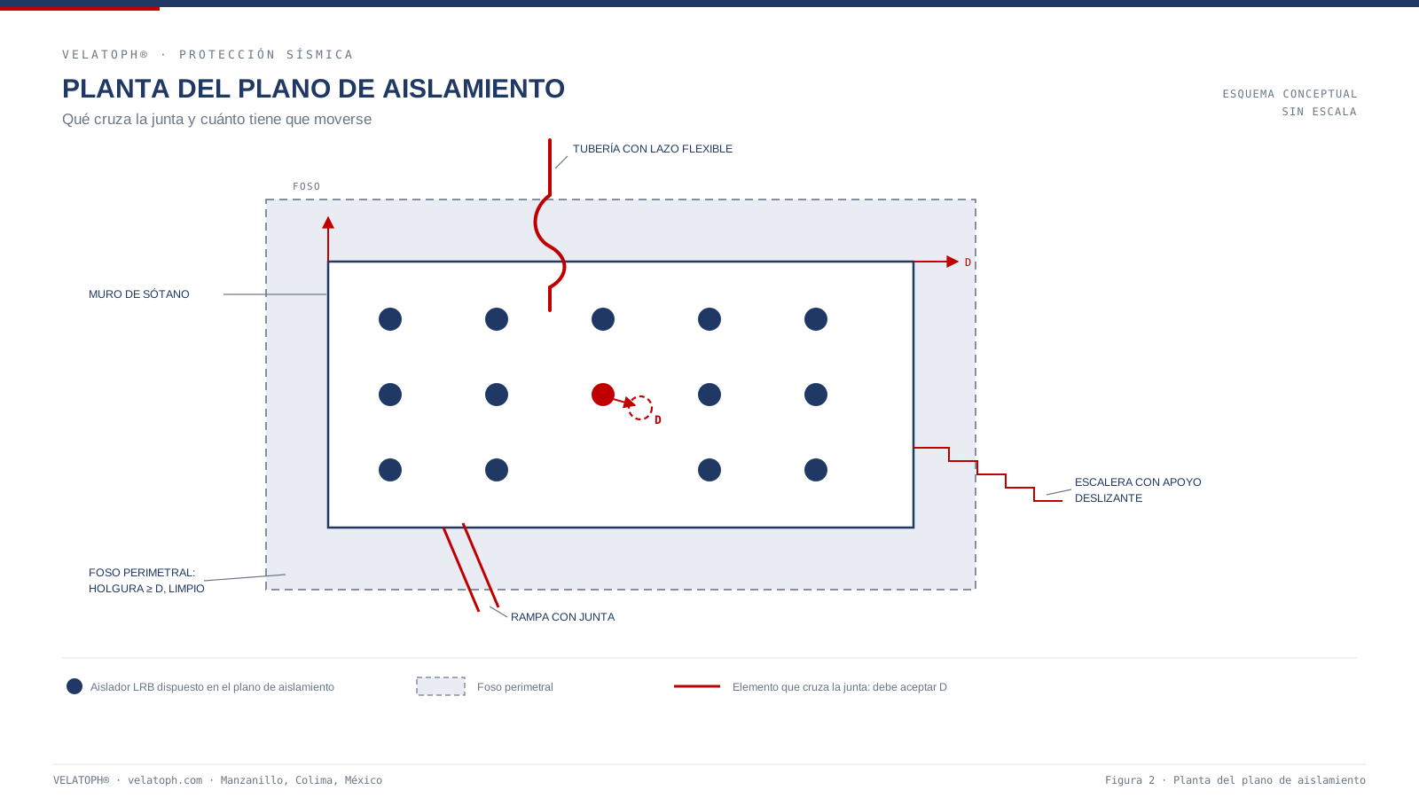
Un edificio aislado tiene un solo lugar donde se permite el movimiento relativo grande: la interfaz entre subestructura y superestructura. Todo lo que cruce ese plano —tubería, ductos, escaleras, rampas, fachadas— debe aceptar el desplazamiento de diseño D, más la tolerancia de construcción y el margen por torsión.
En prefabricado, la posición del plano decide qué se mueve. Si el aislamiento va bajo las columnas, la fachada viaja con la estructura y la junta por resolver es la del zócalo contra el piso exterior. Si va sobre muros de sótano, cada penetración que cruza esa cota necesita su propio detalle.
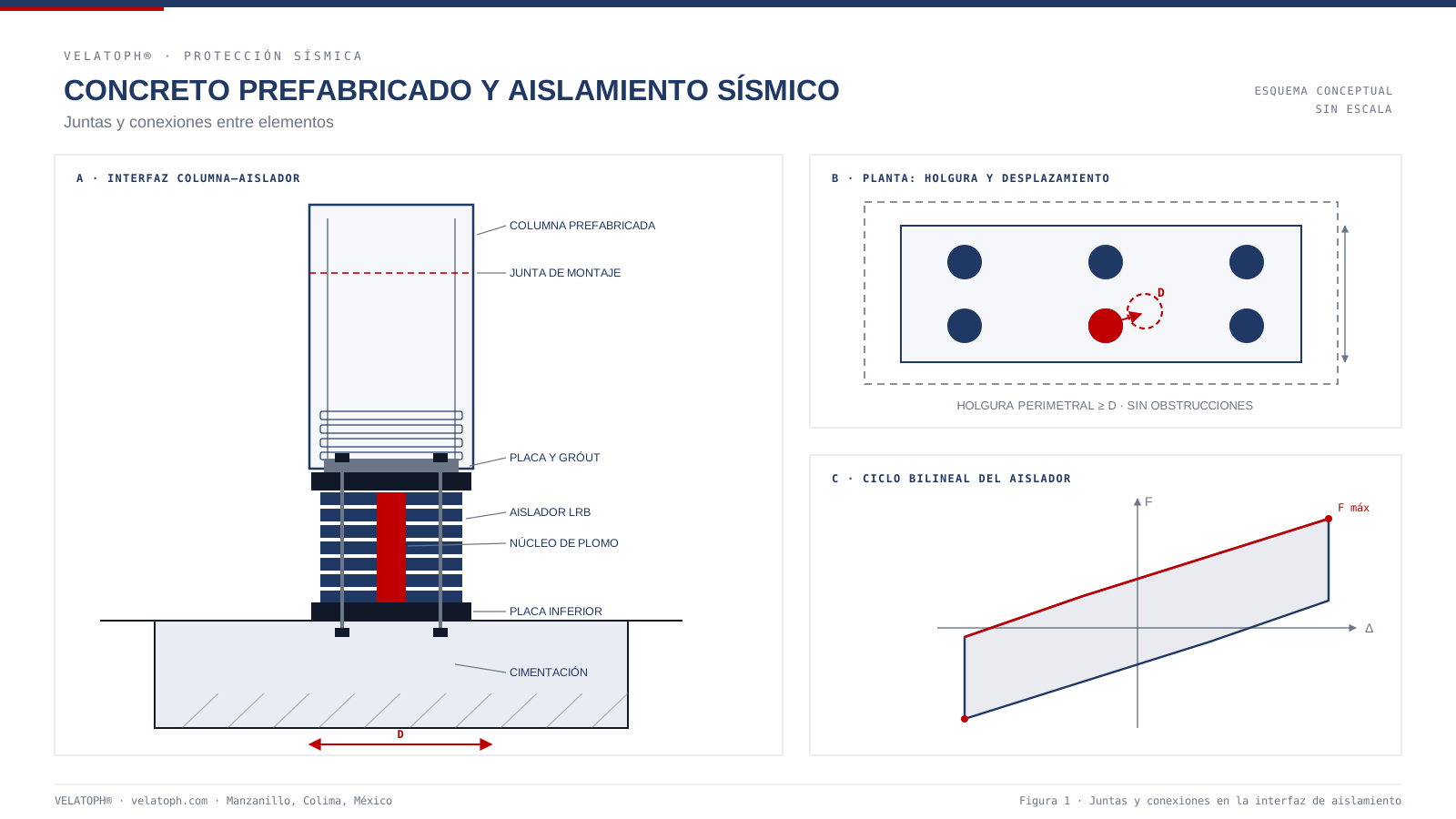
El foso perimetral no es acabado: es holgura. Se dimensiona con D, se protege para que no entre escombro y se revisa. Un foso lleno de arena es una restricción que el modelo no contempló, y ninguna conexión está diseñada para eso.
Las cuatro interfaces del aislador
Cada aislador tiene dos placas y cuatro interfaces: placa superior–aislador, aislador–placa inferior, placa–columna y placa–cimentación. Las cuatro transfieren axial, cortante y momento, y algunas también tensión cuando el volteo descarga un extremo.
En una columna prefabricada, la placa superior se embebe o se atornilla al elemento. El concreto bajo la placa debe confinarse con estribos y revisarse por aplastamiento y punzonamiento; VELATOPH® especifica concreto de contacto de f'c ≥ 250 kg/cm², pero esa cifra no sustituye la revisión local. Los pernos se dimensionan por cortante y arrancamiento, con longitud de anclaje suficiente.
Dos reglas de obra se olvidan: no soldar cerca del elastómero —el calor daña el hule y el plomo sin que se vea— y respetar la secuencia. La columna se iza sobre topes provisionales, el aislador no recibe carga excéntrica durante el montaje, la nivelación se verifica antes de colar el grout y los bloqueos se liberan al final.
Diafragmas: losas alveolares y capa de compresión
Una losa alveolar es excelente para carga vertical y mala para diafragma si se confía sólo en el contacto entre piezas. La fuerza horizontal se transmite por la capa de compresión, por conectores en las juntas o por ambos; sin eso, cada pieza trabaja por su cuenta y la continuidad es una suposición del modelo.
La junta tiene dos familias. La húmeda, con colado en sitio, restituye continuidad pero trae retracción y curado. La seca, con placas soldadas o pernos, concentra la demanda en pocos puntos y centra la revisión en la placa de respaldo, la soldadura y el concreto alrededor. Ninguna es mejor en abstracto.
El aislamiento no sustituye este diseño: baja la demanda, no la elimina. En un edificio aislado el modo de falla suele ser de desplazamiento —pérdida de apoyo, junta que se cierra, panel que golpea— más que de resistencia.
Tolerancias: dos culturas en el mismo nudo
El prefabricado vive con tolerancias de orden centimétrico: posición de insertos, verticalidad, longitud de piezas. El aislador vive con tolerancias de orden milimétrico: nivel, posición en planta, paralelismo. El encuentro se resuelve con placas de nivelación, calzas metálicas y mortero de alta resistencia, no con rellenos de espesor variable.
| Qué se controla | Cómo se corrige | Cuándo se verifica |
|---|---|---|
| Nivel de la placa de asiento | Calzas metálicas y grout de alta resistencia | Antes de izar la columna |
| Posición en planta del anclaje | Plantilla de montaje y verificación topográfica | Antes de colar la cimentación |
| Verticalidad de la columna | Ajuste con tirantes y calzas antes del grout | Antes de liberar la grúa |
| Holgura del foso | Dimensionado con D y limpieza final | Al cerrar obra y en cada inspección |
| Luz libre de instalaciones | Holgura ≥ D más tolerancia, con lazo flexible | Antes de tapar registros |
| Paralelismo entre placas | Revisión con nivel y galgas antes de cargar | Antes de transferir carga al aislador |
Lo que enseñó Emilia
El sismo de Emilia (norte de Italia, mayo de 2012) es caso de estudio obligado del prefabricado industrial. Las naves colapsaron sobre todo por pérdida de apoyo en las conexiones viga-columna y por uniones que dependían de la fricción y del asiento, no de un dispositivo mecánico; también fallaron paneles de fachada mal anclados. El informe del Centro Común de Investigación y el trabajo de Bournas, Negro y Taucer lo documentan.
La lección no es que el aislamiento hubiera evitado el colapso —esos edificios no estaban aislados—, sino que la conexión sigue siendo el punto débil cuando la demanda baja. Una unión que funciona por gravedad y fricción no mejora porque la aceleración se reduzca: sigue sin tener trayectoria de carga explícita. Y el asiento es geometría, no resistencia: si el movimiento relativo lo supera, la viga cae aunque el concreto esté sano.
Estudios recientes sobre marcos prefabricados aislados con conectores de caja muestran lo mismo desde otro lado: el desempeño global mejora, pero depende de la capacidad y ductilidad del conector.
Lista de verificación para un proyecto prefabricado aislado
- ¿Está definido el plano de aislamiento y todo lo que lo cruza?
- ¿La conexión aislador–columna toma cortante, momento y tensión por volteo?
- ¿El concreto bajo la placa está confinado y revisado por punzonamiento?
- ¿El diafragma tiene capa de compresión o conectores, no sólo contacto?
- ¿El asiento de cada viga tolera el desplazamiento relativo?
- ¿Las tolerancias de montaje son compatibles con las del aislador?
- ¿Hay topes provisionales y secuencia escrita de liberación?
- ¿La limpieza del foso está en el manual de mantenimiento?
En VELATOPH®
VELATOPH® fabrica en Manzanillo, Colima, aisladores LRB de 300 a 1,500 mm de diámetro, carga vertical de diseño de 500 a 50,000 kN y amortiguamiento efectivo del 20 al 35%; LDRB de 300 a 1,200 mm y 3 a 5%; y DEF de 50 a 5,000 kN. El diseño se apoya en ASCE 7-22, ISO 22762, NTC-CDMX 2023 y CFE-Sismo 2015, y se documenta con el protocolo de ensayo del proyecto.
Si proyectas o revisas un edificio prefabricado aislado, ofrecemos una evaluación técnica gratuita por WhatsApp. También puedes leer las notas sobre la junta de separación y el foso, el desplazamiento máximo del aislador y la interacción suelo-estructura.
Fuentes
- ASCE. ASCE/SEI 7-22, Minimum Design Loads and Associated Criteria for Buildings and Other Structures, capítulo 17 (estructuras aisladas). asce.org
- ACI. ACI 318-19, Building Code Requirements for Structural Concrete, §16.2 (conexiones de miembros prefabricados) e integridad estructural. concrete.org
- ISO. ISO 22762-1:2024, Elastomeric seismic-protection isolators — Part 1: Test methods. iso.org
- Comisión Europea, Centro Común de Investigación. Performance of Industrial Buildings during the Emilia Earthquakes in Northern Italy and Recommendations for their Strengthening. publications.jrc.ec.europa.eu
- Bournas, D. A., Negro, P. y Taucer, F. The Emilia earthquake: seismic performance of precast reinforced concrete buildings. UCL Discovery. discovery.ucl.ac.uk
- MDPI. Roof Isolation and Girder-to-Column Dissipative Connections in Seismic Design of Precast R/C Structures, Infrastructures 5(11):104. mdpi.com
- Engineering Structures. Experimental study and seismic assessment on base isolated precast concrete frame structure with box connectors. sciencedirect.com
- CPI Worldwide. Ductile connection for the seismic retrofitting of precast buildings. cpi-worldwide.com
Artículo de carácter general y educativo; no sustituye el diseño ni la revisión de un ingeniero responsable de cada proyecto, ni las indicaciones de la autoridad competente.
Precast concrete is not a different material: it is a way of building in which the structure is assembled from pieces that arrive finished and are joined on site. Its seismic behavior depends less on the column section than on what happens at the joint: a well-detailed building behaves as a frame; a poorly connected one, as a stack of resting pieces.
When that building is isolated at its base, the distribution of demand changes. The superstructure moves almost as a rigid body, interstory drift drops and many connections stop working in the inelastic range. But the shear does not disappear: it is transferred in full at the isolation interface, and the displacement is concentrated there as well. The structure is simpler to analyze and far more demanding at two places: the isolator connection and the joint around it.
What changes and what does not when the building is isolated
With an isolated period on the order of two to four seconds, floor accelerations drop, and with them the inertial forces reaching beam-column connections, façade anchors and contents. In a precast frame, many joints designed for yielding in a fixed-base building may remain in the elastic range.
What does not change is the logic: the diaphragm still has to exist. Horizontal forces at each level must reach the isolation plane, and for that the slab needs continuity or mechanical connectors. ACI 318-19, §16.2, requires connections between precast elements to resist design forces and accommodate erection tolerances; structural integrity provisions still apply.
The isolation plane: the joint that governs
An isolated building has a single location where large relative movement is permitted: the interface between substructure and superstructure. Everything that crosses that plane —pipes, ducts, stairs, ramps, façades— must accommodate the design displacement D, plus construction tolerance and the margin for torsion.
In precast construction, the position of the plane decides what moves. If isolation sits below the columns, the façade travels with the structure and the joint to resolve is the one at the plinth against the exterior floor. If it sits above basement walls, every penetration crossing that elevation needs its own detail.
The perimeter moat is not a finish: it is clearance. It is sized with D, protected against debris and inspected. A moat filled with sand is a restraint the model did not contemplate, and no connection is designed for that.
The four interfaces of the isolator
Every isolator has two plates and four interfaces: top plate–isolator, isolator–bottom plate, plate–column and plate–foundation. All four transfer axial, shear and moment, and some also tension when overturning unloads one end.
In a precast column, the top plate is embedded in or bolted to the element. The concrete beneath the plate must be confined with hoops and checked for bearing and punching; VELATOPH® specifies contact concrete of f'c ≥ 250 kg/cm², but that figure does not replace the local check. Bolts are sized for shear and pull-out, with sufficient anchorage length.
Two site rules get forgotten: do not weld near the elastomer —heat damages the rubber and the lead invisibly— and respect the sequence. The column is lifted onto temporary restraints, the isolator receives no eccentric load during erection, leveling is verified before grouting and locking devices are released at the end.
Diaphragms: hollow-core slabs and topping
A hollow-core slab is excellent for vertical load and poor as a diaphragm if it relies only on contact between units. Horizontal force is transferred through the topping, through connectors in the joints or through both; without that, each unit works on its own and continuity is an assumption of the model.
The joint has two families. The wet joint, cast on site, restores continuity but brings shrinkage and curing. The dry joint, with welded plates or bolts, concentrates demand at a few points and focuses review on the backing plate, the weld and the surrounding concrete. Neither is better in the abstract.
Isolation does not replace this design: it lowers demand, it does not remove it. In an isolated building the failure mode is usually one of displacement —loss of support, a joint closing, a panel striking— rather than of strength.
Tolerances: two cultures in the same joint
Precast construction lives with tolerances on the order of centimeters: insert position, plumbness, member length. The isolator lives with tolerances on the order of millimeters: level, plan position, parallelism. The meeting point is resolved with leveling plates, steel shims and high-strength mortar, not with variable-thickness fill.
| What is controlled | How it is corrected | When it is verified |
|---|---|---|
| Seat plate level | Steel shims and high-strength grout | Before lifting the column |
| Anchor plan position | Setting template and survey check | Before pouring the foundation |
| Column plumbness | Adjustment with guys and shims before grouting | Before releasing the crane |
| Moat clearance | Sized with D and final cleaning | At closeout and at every inspection |
| Clearance of services | Clearance ≥ D plus tolerance, with flexible loop | Before closing access panels |
| Parallelism between plates | Checked with level and feeler gauges before loading | Before transferring load to the isolator |
What Emilia taught
The Emilia earthquake (northern Italy, May 2012) is a mandatory case study for industrial precast construction. The warehouses collapsed mainly through loss of support at beam-column connections and through joints that relied on friction and seat length rather than on a mechanical device; poorly anchored façade panels also failed. The Joint Research Centre report and the work by Bournas, Negro and Taucer document it.
The lesson is not that isolation would have prevented the collapse —those buildings were not isolated— but that the connection remains the weak point once demand drops. A joint that works through gravity and friction does not improve because acceleration is halved: it still has no explicit load path. And seat length is geometry, not strength: if relative movement exceeds it, the beam falls even when the concrete is sound.
Recent studies on isolated precast frames with box connectors show the same from another angle: global performance improves, but it depends on the connector's capacity and ductility.
Checklist for an isolated precast project
- Is the isolation plane defined, together with everything that crosses it?
- Does the isolator–column connection carry shear, moment and overturning tension?
- Is the concrete beneath the plate confined and checked for punching?
- Does the diaphragm have topping or connectors, not just contact?
- Does each beam seat accommodate the relative displacement?
- Are erection tolerances compatible with the isolator's tolerances?
- Are there temporary restraints and a written release sequence?
- Is moat cleaning part of the maintenance manual?
At VELATOPH®
VELATOPH® manufactures in Manzanillo, Colima, LRB isolators from 300 to 1,500 mm in diameter, design vertical load from 500 to 50,000 kN and effective damping from 20% to 35%; LDRB from 300 to 1,200 mm and 3% to 5%; and DEF from 50 to 5,000 kN. Design relies on ASCE 7-22, ISO 22762, NTC-CDMX 2023 and CFE-Sismo 2015, and is documented with the project's test protocol.
If you design or review an isolated precast building, we offer a free technical assessment via WhatsApp. You can also read the notes on the seismic joint and moat, maximum isolator displacement and soil-structure interaction.
Sources
- ASCE. ASCE/SEI 7-22, Minimum Design Loads and Associated Criteria for Buildings and Other Structures, Chapter 17 (seismically isolated structures). asce.org
- ACI. ACI 318-19, Building Code Requirements for Structural Concrete, §16.2 (connections between precast members) and structural integrity. concrete.org
- ISO. ISO 22762-1:2024, Elastomeric seismic-protection isolators — Part 1: Test methods. iso.org
- European Commission, Joint Research Centre. Performance of Industrial Buildings during the Emilia Earthquakes in Northern Italy and Recommendations for their Strengthening. publications.jrc.ec.europa.eu
- Bournas, D. A., Negro, P., and Taucer, F. The Emilia earthquake: seismic performance of precast reinforced concrete buildings. UCL Discovery. discovery.ucl.ac.uk
- MDPI. Roof Isolation and Girder-to-Column Dissipative Connections in Seismic Design of Precast R/C Structures, Infrastructures 5(11):104. mdpi.com
- Engineering Structures. Experimental study and seismic assessment on base isolated precast concrete frame structure with box connectors. sciencedirect.com
- CPI Worldwide. Ductile connection for the seismic retrofitting of precast buildings. cpi-worldwide.com
General, educational article; it does not replace the design or review by an engineer responsible for each project, or the instructions of the competent authority.