Un tanque de almacenamiento no es un edificio con paredes curvas. Contiene una masa líquida enorme y su respuesta sísmica combina el movimiento de la estructura con el del fluido. En una planta industrial convive con tuberías, escaleras, instrumentos y equipos que deben seguir funcionando. Por eso el aislamiento sísmico de tanques y estructuras industriales no se resuelve copiando el detalle de un edificio: se decide caso por caso, mirando geometría, masa, contenido y, sobre todo, conexiones.
La pregunta no es si cabe un aislador bajo el tanque, sino si el conjunto —tanque, fluido, base, aisladores, tuberías y soportes— puede moverse como un sistema y seguir siendo seguro. Si no puede, el detalle traslada el problema a la tubería, al anclaje o al propio tanque.
Qué hace distinto a un tanque
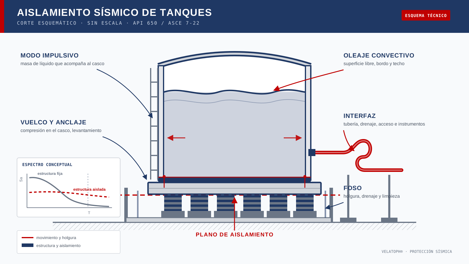
Bajo excitación sísmica, el líquido se separa en dos componentes. La masa impulsiva se mueve con el casco y carga la pared, el fondo y la cimentación. La masa convectiva forma el oleaje en la superficie libre, con periodo largo y amortiguamiento bajo. API 650, anexo E, es la referencia más difundida para tanques de acero soldados, verticales y de fondo plano; la guía de la NZSEE amplía el tratamiento a tanques de concreto y otros materiales. Ambas separan presión, vuelco y oleaje.
El casco es una lámina delgada. Su falla típica no es un agrietamiento de concreto, sino un pandeo por compresión en la unión con el fondo —el elephant foot—, además de fallas en anclajes, levantamiento del fondo, daño en la unión casco-fondo y pérdida de estanqueidad. Si no hay bordo libre suficiente, el oleaje puede golpear el techo, derramar producto o dañar un techo flotante. Un modelo de edificio no captura esos mecanismos.
Dos modos, dos problemas
El modo impulsivo suele tener un periodo corto; el convectivo, uno mucho más largo, gobernado por la gravedad y por el diámetro del tanque. El aislamiento alarga el periodo impulsivo y reduce la aceleración espectral que lo excita, y por eso puede proteger el casco. Pero el modo convectivo no se “aísla” igual: el oleaje sigue siendo un fenómeno de superficie libre y, si el periodo aislado queda cerca del convectivo, ambos pueden acoplarse y amplificar el movimiento del líquido.
Ese acoplamiento exige un modelo dinámico con el fluido incluido, no un espectro de edificio corregido. También obliga a revisar la componente vertical: la mayoría de los sistemas trabajan en horizontal, mientras el tanque, el techo y sus soportes siguen sometidos a aceleración vertical. En tanques altos y esbeltos, el vuelco y la estabilidad de la base pueden gobernar antes que la fuerza sobre el casco.
Aislar el tanque, no solo el equipo
Para llevar un tanque de fondo plano a un plano de aislamiento hace falta una base que distribuya la carga. Ese anillo o losa rígida debe recibir el peso del tanque y del líquido, las cargas de vuelco y las acciones de los aisladores, y transmitirlas sin deformarse de forma incompatible con el casco. La unión entre casco y base no es un detalle menor: una base flexible puede introducir esfuerzos locales que el cálculo global no muestra.
Después vienen los aisladores. Un elastómero trabaja bien a compresión, pero no debe quedar sometido a tracción; en un tanque con vuelco eso exige restricciones de levantamiento o suficiente carga gravitacional. Un péndulo de fricción requiere controlar el levantamiento y proteger la superficie deslizante. El foso debe acomodar el desplazamiento de diseño y el máximo, y estar limpio y drenado. Ese espacio suele estar ocupado por tuberías y cimentaciones vecinas.
La interfaz es el proyecto
En un edificio aislado, las conexiones que cruzan la junta son importantes. En un tanque industrial son, con frecuencia, la parte más difícil. Tubería, venteo, agua contra incendio, drenaje, instrumentación, escaleras y plataformas deben tener holgura o juntas flexibles, y resistir su carga sin restringir el tanque.
| Interfaz | Qué exige el aislamiento | Error típico |
|---|---|---|
| Tubería de proceso | Flexibilidad, juntas de expansión o lazos; soportes que permitan el movimiento | Conectar rígido y confiar en que la tubería “cederá” |
| Escaleras y plataformas | Uniones deslizantes o apoyos independientes | Fijarlas al tanque y a una estructura exterior a la vez |
| Instrumentación y cables | Trayectorias con holgura y longitud suficiente | Dejar el cable tenso entre dos puntos |
| Drenaje y cubeto | Juntas flexibles, pendientes estables y volumen contenido | Rigidizar el drenaje y anular el movimiento en ese punto |
| Protección contra incendio | Materiales y detalles compatibles con el riesgo del contenido | Exponer el elastómero a un charco de hidrocarburo o a calor radiante |
La protección contra incendio merece atención propia. En una instalación con hidrocarburos, el aislador puede quedar expuesto a fuego de charco, calor radiante o derrame caliente. Los elastómeros y sus cubiertas deben protegerse o seleccionarse para esa condición, y el drenaje debe evacuar el producto sin acumularlo bajo el tanque. Debe formar parte del diseño, no resolverse en obra.
Estructuras y equipos industriales
No todo elemento de una planta se beneficia igual. Un tanque bajo y ancho, dominado por el oleaje, es distinto de un recipiente esbelto o de un equipo sensible sobre plataforma. En equipos rotativos, el aislamiento debe convivir con la vibración de operación, la alineación y las cargas térmicas; una plataforma demasiado flexible puede crear problemas que el sismo no planteaba.
También es distinto aislar un edificio que aislar un equipo dentro de él. Aislar la estructura completa da más control sobre la interfaz, pero puede ser desproporcionado para una nave grande y poco crítica. Aislar solo el equipo puede ser eficiente si la plataforma es estable, hay holgura y todas las conexiones lo acompañan. La decisión depende de la función que deba preservarse: seguridad, contención, continuidad o protección de un activo específico.
Cuándo conviene y qué revisar
El aislamiento tiene más sentido cuando la estructura es rígida, el contenido es peligroso o costoso, la instalación debe seguir operando y el suelo no impone un periodo largo que compita con el sistema. Pierde atractivo cuando el tanque es muy bajo y ancho, cuando el oleaje ya gobierna sin bordo libre, cuando la tubería no puede hacerse flexible o cuando el fuego y la falta de acceso impiden inspeccionar el dispositivo.
- Definir el desempeño esperado: seguridad, contención, operación o protección del equipo.
- Caracterizar la masa total, incluida la masa hidrodinámica.
- Revisar periodo impulsivo, convectivo y su acoplamiento con el periodo aislado.
- Comprobar bordo libre, oleaje, vuelco, anclaje, estabilidad e interfaz de tuberías y acceso.
- Evaluar fuego, corrosión, temperatura y salinidad; prever inspección y reemplazo.
Normativa y verificación
ASCE 7-22, capítulo 17, establece requisitos para estructuras aisladas; para tanques, API 650, anexo E, y la guía de la NZSEE aportan los criterios del recipiente y del fluido. Los aisladores elastoméricos se prueban conforme a ISO 22762, y los dispositivos antisísmicos cuentan con EN 15129. Ninguna norma sustituye la revisión conjunta: tanque, base, aisladores y conexiones forman un sistema.
La verificación debería incluir un modelo con la masa del líquido, la no linealidad de los aisladores, efectos verticales, torsión accidental, estabilidad de la base y cargas de las conexiones. También conviene revisar la secuencia de construcción y la prueba hidrostática: llenar el tanque antes de que el sistema esté completo cambia las condiciones de diseño. Si el tanque ya existe, la evaluación debe partir de lo que hay —anclajes, corrosión, fundación, tuberías— y no de lo que la memoria supone.
En VELATOPH®
VELATOPH® fabrica en Manzanillo, Colima, aisladores elastoméricos LRB y LDRB, aisladores pendulares FPS y DFP, y disipadores DEF y DVF. En un proyecto industrial, el punto de partida es la carga real por apoyo, la geometría del tanque o del equipo y el espacio disponible; después se resuelve la interfaz con la instalación existente.
Si evalúas aislar un tanque o un equipo industrial, ofrecemos una evaluación técnica gratuita por WhatsApp. También puedes revisar la nota sobre aislamiento de equipos, la guía de protección ignífuga y el análisis de costo del aislamiento.
Fuentes
- American Petroleum Institute. API Standard 650, Welded Tanks for Oil Storage, 13.ª edición, anexo E (diseño sísmico). api.org
- NZSEE. Seismic Design of Storage Tanks, recomendaciones del grupo de estudio, 2009. nzsee.org.nz
- ASCE. ASCE/SEI 7-22, Minimum Design Loads and Associated Criteria for Buildings and Other Structures, capítulo 17. asce.org
- ISO. ISO 22762-1:2024, Elastomeric seismic-protection isolators — Part 1: Test methods. iso.org
- Spritzer, J. M. y Guzey, S. “Review of API 650 Annex E: Design of large steel welded aboveground storage tanks excited by seismic loads”. Thin-Walled Structures. doi.org
Artículo de carácter general y educativo; no sustituye el diseño ni la revisión de un ingeniero responsable de cada instalación, ni las indicaciones de la autoridad competente.
A storage tank is not a building with curved walls. It holds an enormous liquid mass, and its seismic response combines the motion of the structure with that of the fluid. In an industrial plant it also coexists with piping, stairs, instruments and equipment that must keep working. That is why seismic isolation of tanks and industrial structures cannot be solved by copying a building detail: it is decided case by case, looking at geometry, mass, contents and, above all, connections.
The question is not whether a bearing can be placed under the tank, but whether the whole system —tank, fluid, base, bearings, piping and supports— can move together and remain safe. If it cannot, the detail transfers the problem to the piping, the anchorage or the tank itself.
What makes a tank different
Under seismic excitation, the liquid separates into two components. The impulsive mass moves with the shell and loads the wall, the bottom and the foundation. The convective mass forms the wave at the free surface, with a long period and low damping. API 650, Annex E, is the most widely used reference for welded, vertical, flat-bottom steel tanks; the NZSEE guideline extends the treatment to concrete and other tanks. Both separate pressure, overturning and wave height.
The shell is a thin plate. Its typical seismic failure is not concrete cracking but compression buckling at the shell-to-bottom junction —elephant foot buckling— along with anchor failure, bottom uplift, shell-to-bottom damage and loss of containment. Without enough freeboard, the wave can hit the roof, spill product or damage a floating roof. A building model does not capture these mechanisms.
Two modes, two problems
The impulsive mode usually has a short period; the convective one is much longer, governed by gravity and tank diameter. Isolation lengthens the impulsive period and reduces the spectral acceleration that excites it, which is why it can protect the shell. But the convective mode is not “isolated” in the same way: sloshing remains a free-surface phenomenon and, if the isolated period approaches the convective period, the two can couple and amplify liquid motion.
That coupling calls for a dynamic model that includes the fluid, not a corrected building spectrum. It also requires checking the vertical component: most systems work horizontally, while the tank, roof and supports still experience vertical acceleration. In tall, slender tanks, overturning and base stability can govern before shell force does.
Isolate the tank, not just the equipment
Taking a flat-bottom tank to an isolation plane requires a base that distributes the load. That rigid ring or slab must receive the weight of the tank and liquid, the overturning loads and the bearing actions, and transmit them without deforming incompatibly with the shell. The shell-to-base connection is not a minor detail: a flexible base can introduce local stresses that the global analysis does not show.
Then come the bearings. An elastomer works well in compression but should not be left in tension; in a tank subject to overturning this may require uplift restraints or sufficient gravity load. A friction pendulum requires uplift control and protection of the sliding surface. The moat must accommodate the design and maximum displacements and remain clean and drained. That space is often occupied by piping and nearby foundations.
The interface is the project
In an isolated building, the connections crossing the joint matter. In an industrial tank they are often the hardest part. Process piping, venting, fire water, drainage, instrumentation, stairs and platforms must have clearance or flexible joints, and carry their own load without restraining the tank.
| Interface | What isolation requires | Typical mistake |
|---|---|---|
| Process piping | Flexibility, expansion joints or loops; supports that allow movement | Rigid connection, assuming the pipe will “give” |
| Stairs and platforms | Sliding joints or independent supports | Fixing them to both the tank and an external structure |
| Instrumentation and cables | Slack routes and sufficient length | Leaving a cable taut between two points |
| Drainage and containment | Flexible joints, stable slopes and contained volume | Making the drain rigid and cancelling movement there |
| Fire protection | Materials and details compatible with the contents hazard | Exposing the elastomer to a hydrocarbon pool or radiant heat |
Fire protection deserves its own attention. In a hydrocarbon facility, the bearing may be exposed to pool fire, radiant heat or a hot spill. Elastomers and their covers must be protected or selected for that condition, and drainage must remove product without accumulating it under the tank. It is a design input, not something to solve on site.
Industrial structures and equipment
Not every plant element benefits equally. A shallow, wide tank dominated by sloshing is different from a slender vessel or sensitive equipment on a platform. In rotating equipment, isolation must coexist with operating vibration, alignment and thermal loads; an overly flexible platform can create problems the earthquake did not.
Isolating a building is also different from isolating equipment inside it. Isolating the whole structure gives more control over the interface but may be disproportionate for a large, non-critical shed. Isolating only the equipment can be efficient if the platform is stable, there is room to move and all connections follow it. The decision depends on the function to preserve: safety, containment, continuity or protection of a specific asset.
When it makes sense and what to check
Isolation makes more sense when the structure is stiff, the contents are hazardous or costly, the plant must keep operating and the soil does not impose a long period that competes with the system. It is less attractive when the tank is shallow and wide, sloshing already governs without freeboard, the piping cannot be made flexible, or fire and lack of access prevent inspection of the device.
- Define the expected performance: safety, containment, operation or equipment protection.
- Characterize total mass, including hydrodynamic mass.
- Check impulsive and convective periods and their coupling with the isolated period.
- Verify freeboard, sloshing, overturning, anchorage, stability and the piping and access interface.
- Assess fire, corrosion, temperature and salinity; plan inspection and replacement.
Standards and verification
ASCE 7-22, Chapter 17, sets requirements for seismically isolated structures; for tanks, API 650, Annex E, and the NZSEE guideline provide the vessel and fluid criteria. Elastomeric isolators are tested under ISO 22762, and anti-seismic devices have EN 15129. No standard replaces the combined review: tank, base, bearings and connections form one system.
Verification should include a model with the liquid mass, bearing nonlinearity, vertical effects, accidental torsion, base stability and connection loads. Construction sequence and hydrostatic testing also deserve review: filling the tank before the system is complete changes the design conditions. If the tank already exists, the assessment must start from what is there —anchors, corrosion, foundation, piping— and not from what the calculation report assumes.
At VELATOPH®
VELATOPH® manufactures in Manzanillo, Colima, LRB and LDRB elastomeric isolators, FPS and DFP pendulum isolators, and DEF and DVF dampers. In an industrial project, the starting point is the actual load per bearing, the geometry of the tank or equipment and the available space; then the interface with the existing plant is resolved.
If you are considering isolating a tank or industrial equipment, we offer a free technical assessment via WhatsApp. You can also read the note on equipment isolation, the guide to fire protection and the analysis of isolation cost.
Sources
- American Petroleum Institute. API Standard 650, Welded Tanks for Oil Storage, 13th edition, Annex E (seismic design). api.org
- NZSEE. Seismic Design of Storage Tanks, study group recommendations, 2009. nzsee.org.nz
- ASCE. ASCE/SEI 7-22, Minimum Design Loads and Associated Criteria for Buildings and Other Structures, Chapter 17. asce.org
- ISO. ISO 22762-1:2024, Elastomeric seismic-protection isolators — Part 1: Test methods. iso.org
- Spritzer, J. M. and Guzey, S. “Review of API 650 Annex E: Design of large steel welded aboveground storage tanks excited by seismic loads”. Thin-Walled Structures. doi.org
General, educational article; it does not replace the design or review by an engineer responsible for each facility, or the instructions of the competent authority.