La Torre Médica de Especialidades de Bahía de Banderas, Nayarit, se levanta sobre uno de los entornos sísmicos más exigentes de México. Frente a esta costa interactúan la placa de Rivera y el bloque de Jalisco, una frontera tectónica que la sismología ha identificado como una brecha o gap sísmico: una zona capaz de generar sismos de magnitud mayor a 7 con una recurrencia estimada de 40 a 45 años. Para un hospital —una instalación que debe seguir operando justo después del sismo— resistir no basta: hay que proteger.
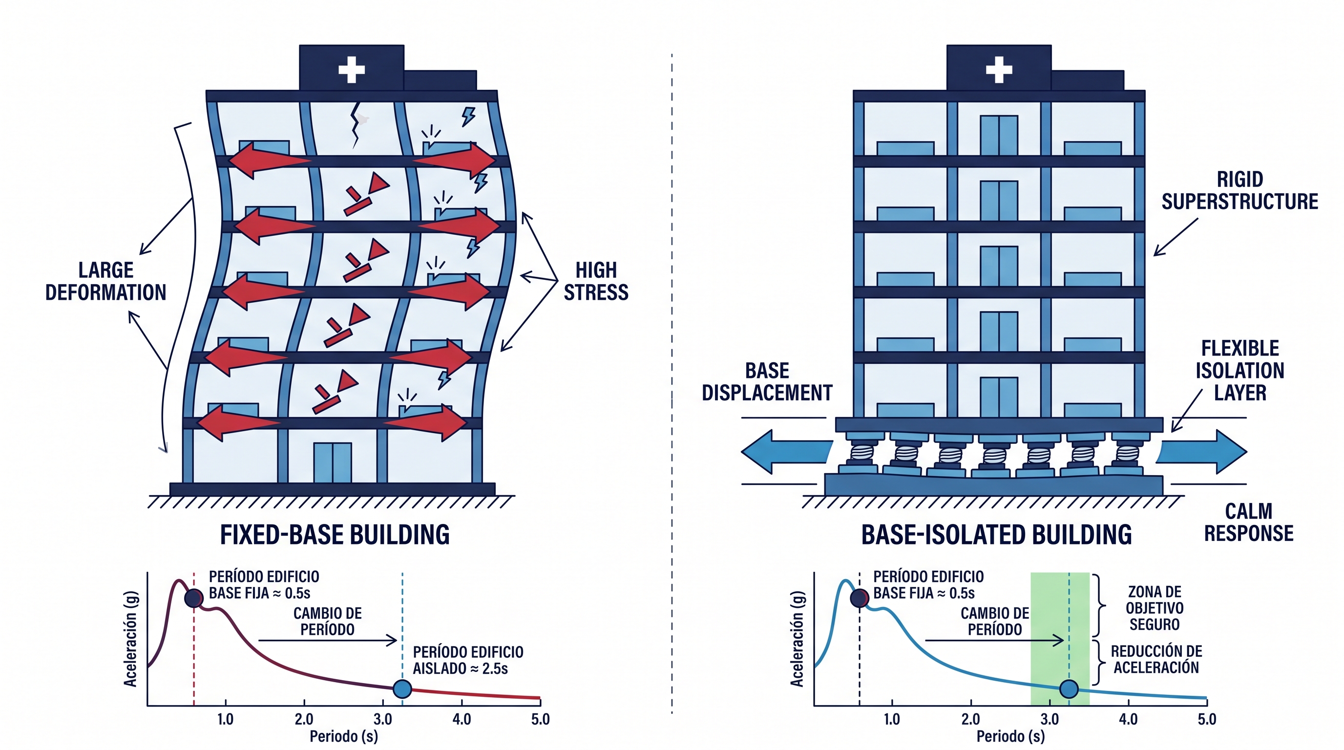
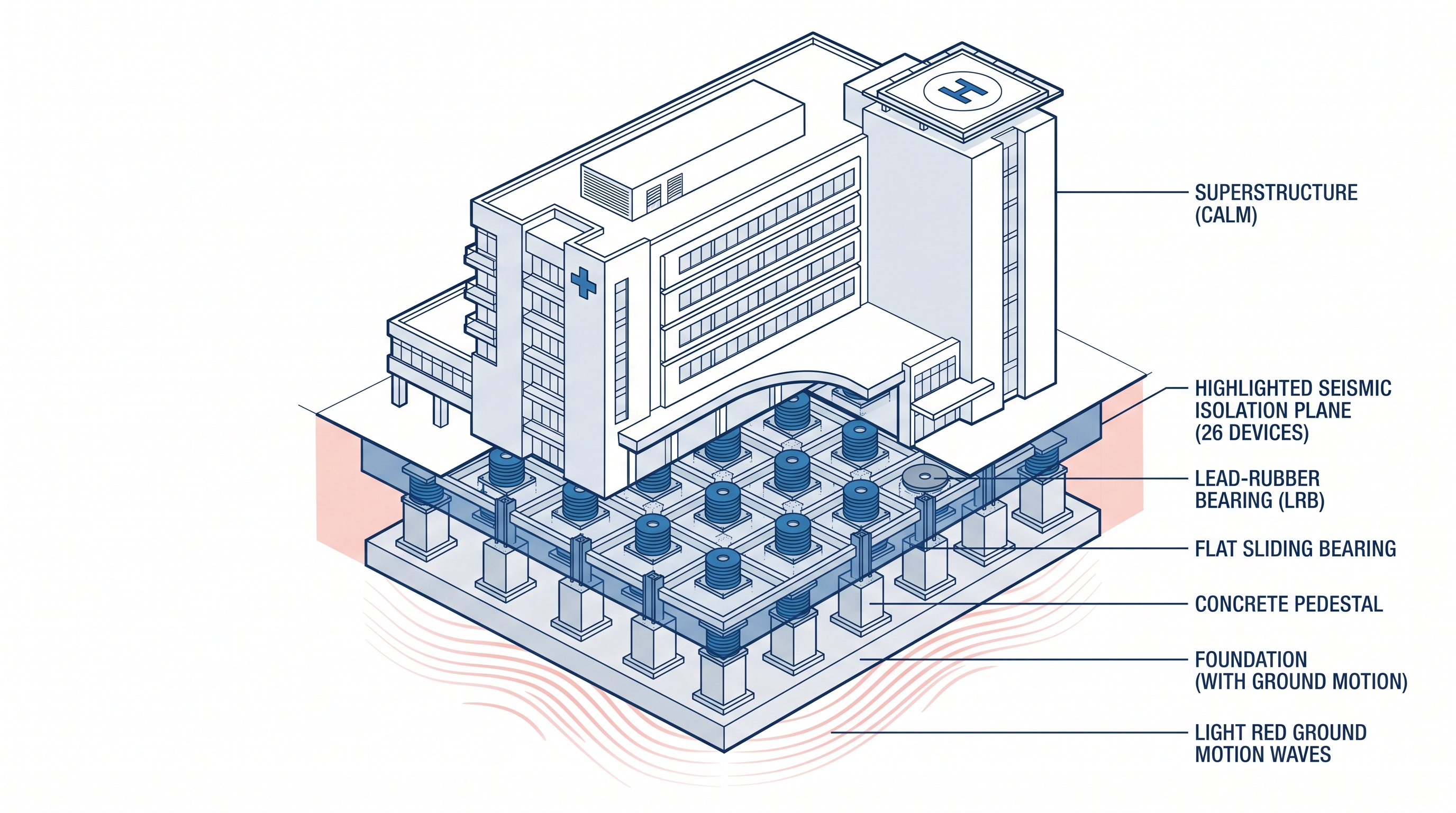
El aislamiento sísmico de base responde a esa exigencia con una idea físicamente simple. En lugar de hacer la estructura más rígida y fuerte para que absorba la energía del sismo, se inserta entre la cimentación y el edificio un plano de dispositivos flexibles que desacoplan la superestructura del movimiento del suelo. Al hacerlo, el periodo natural del conjunto se alarga de forma deliberada —de medio segundo a más de dos segundos y medio— y la aceleración que llega a los pisos cae drásticamente. El edificio se mueve casi como un cuerpo rígido sobre una capa que disipa la energía.
Este artículo recorre, paso a paso, cómo el equipo de ingeniería de VELATOPH® diseñó el sistema de aislamiento de esta torre con el módulo de aislamiento sísmico de Alpha Estructural, su plataforma de cálculo propia, bajo el marco del capítulo 17 de la ASCE 7-22, las NTC-Sismo CDMX 2023 y las AASHTO Guide Specifications for Seismic Isolation Design.
Qué es un aislador LRB
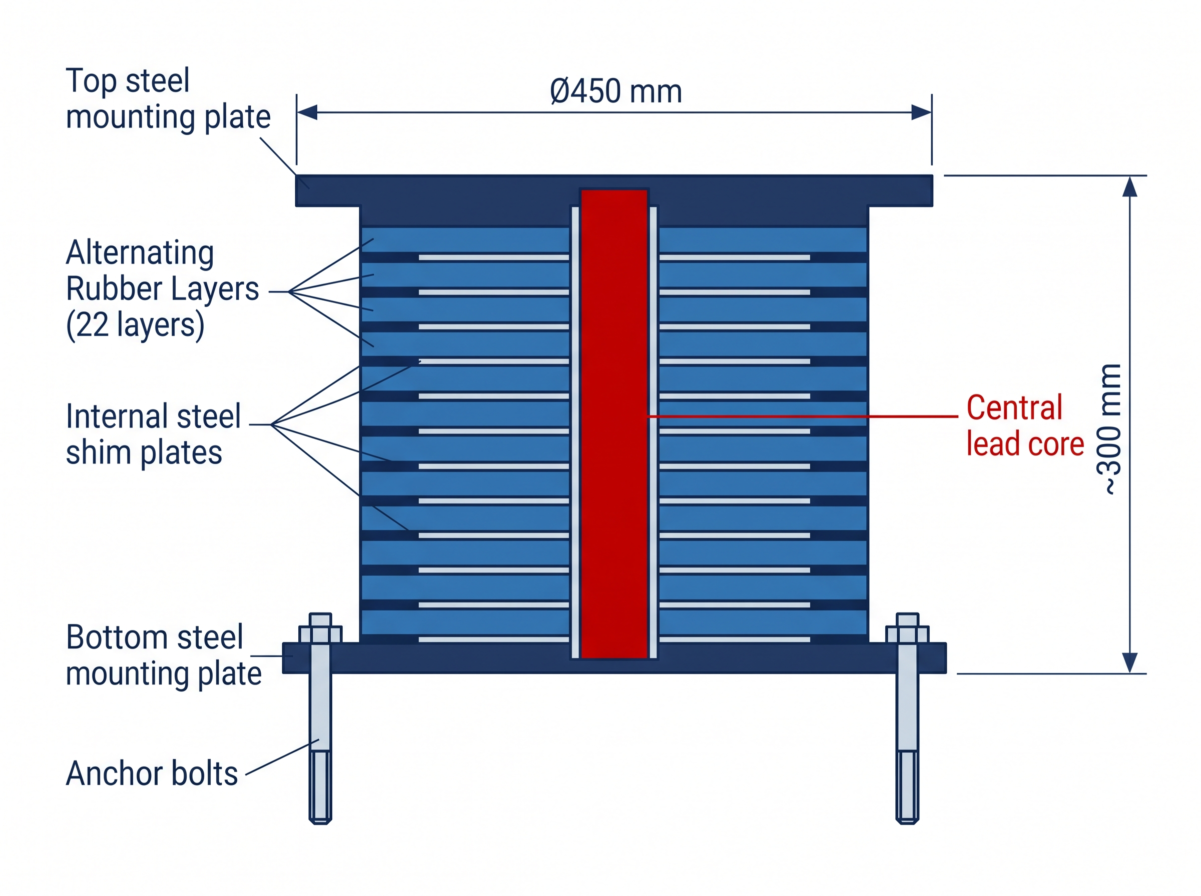
El corazón del sistema es el LRB (Lead-Rubber Bearing, aislador elastomérico con núcleo de plomo). Es un cilindro formado por decenas de capas delgadas de caucho intercaladas con láminas de acero —los shims—, todo confinado entre dos placas de acero que lo conectan a la estructura. Por el centro lo atraviesa un núcleo macizo de plomo.
Cada componente cumple una función precisa:
- Las capas de caucho dan la baja rigidez horizontal que alarga el periodo: el aislador se deforma lateralmente con facilidad.
- Las láminas de acero confinan el caucho e impiden que se abombe bajo el peso del edificio, aportando una enorme rigidez vertical sin restar flexibilidad horizontal.
- El núcleo de plomo es el amortiguador: al deformarse plásticamente en cada ciclo, convierte la energía del sismo en calor y limita el desplazamiento.
- Las placas extremas transmiten la carga vertical y anclan el dispositivo a la estructura.
El comportamiento del LRB se describe con un modelo bilineal: muy rígido al principio —mientras el plomo no ha fluido— y mucho más flexible después, cuando el plomo fluye y la fuerza la gobierna el caucho. De ese modelo salen tres números clave: la rigidez post-fluencia (Kd), que marca la pendiente flexible; la fuerza característica (Qd), que mide cuánta energía disipa el plomo; y la rigidez efectiva (Keff), el promedio que define el periodo del conjunto.
Paso 1 — Definir las demandas
Todo diseño arranca por las demandas que el sistema debe satisfacer. Para esta torre:
- Cargas verticales: el plano de aislamiento soporta un peso de servicio de 1,902.24 ton. Se distingue entre la carga de servicio (la presente de forma permanente) y la carga máxima de diseño (que incluye los efectos sísmicos verticales y de volteo).
- Desplazamientos: un desplazamiento de diseño DD = 18 cm para dimensionar, y un desplazamiento máximo DM = 22 cm para verificar la estabilidad en el sismo extremo.
- Periodo objetivo: ≈ 2.5 s, suficiente para alejar la estructura de la zona de mayor energía del espectro.
- Amortiguamiento objetivo: ≥ 21 %, muy por encima del 5 % de una estructura convencional.
Paso 2 — La distinción clave: servicio vs. diseño
Aquí está el concepto que más errores provoca. El periodo del sistema se calcula con la carga de servicio, porque la masa que realmente vibra durante el sismo es la del peso permanente. En cambio, la resistencia y la estabilidad se verifican con la carga máxima de diseño, que es mayor porque suma los efectos sísmicos. Son dos cargas para dos preguntas distintas: "¿con qué periodo vibra?" y "¿aguanta el peor caso?".
Paso 3 — Dimensionamiento geométrico
Con las demandas claras, se define la geometría: diámetro exterior, espesor total de caucho, número de capas y diámetro del núcleo de plomo. Ambos modelos de esta torre comparten un diámetro exterior de Ø450 mm y 22 capas de caucho de 8 mm (espesor total de caucho tr = 176 mm), con una altura total cercana a 30 cm. El núcleo de plomo varía según la carga: Ø73 mm en el LRB-1, el más cargado, y Ø65 mm en el LRB-2.
Dos factores de forma gobiernan el dimensionamiento:
- El factor de forma primario S1 relaciona el área cargada con el área libre de cada capa de caucho y controla la rigidez vertical del aislador.
- El factor de forma secundario S2 —aquí 2.56— relaciona el diámetro con el espesor total de caucho y controla la estabilidad frente al pandeo: un aislador demasiado esbelto pandearía bajo carga al desplazarse.
La elección del caucho es un compromiso entre periodo, amortiguamiento y tamaño. Un módulo de cortante bajo, G = 0.36 MPa, da la flexibilidad necesaria para alcanzar el periodo objetivo sin recurrir a un dispositivo desproporcionadamente alto; combinado con el núcleo de plomo (fluencia a cortante fyL = 10 MPa), entrega periodo y amortiguamiento en un mismo cuerpo compacto.
Paso 4 — Propiedades dinámicas
Definida la geometría, se calculan las propiedades dinámicas de cada aislador. El plomo aporta la fuerza característica Qd; el caucho confinado aporta la rigidez post-fluencia Kd; juntas definen la rigidez efectiva Keff, el periodo individual T y el amortiguamiento ξ.
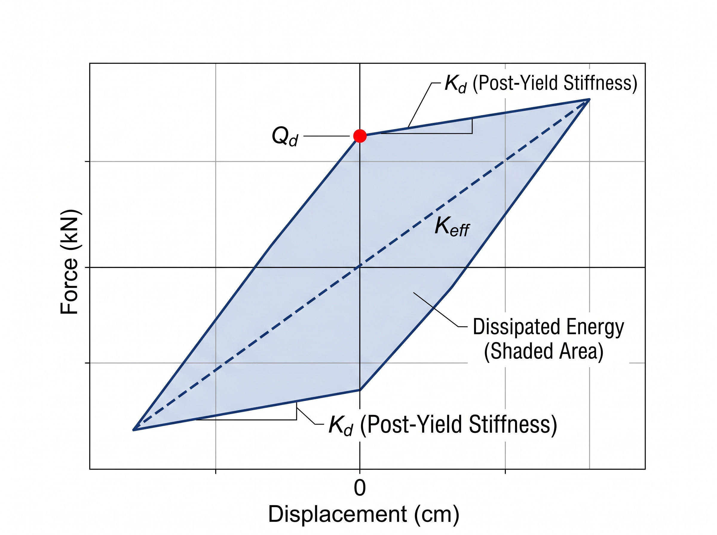
La curva de histéresis bilineal resume todo el comportamiento: cuanto mayor es el área que encierra el lazo, más energía disipa el dispositivo en cada ciclo de carga y descarga. Estos son los resultados de diseño para los dos modelos:
| Parámetro | LRB-1 (×6) | LRB-2 (×14) |
|---|---|---|
| Carga servicio / máxima diseño | 87 / 146.5 ton | 78 / 132 ton |
| Diámetro exterior | Ø450 mm | Ø450 mm |
| Núcleo de plomo | Ø73 mm | Ø65 mm |
| Capas de caucho | 22 × 8 mm (tr = 176 mm) | 22 × 8 mm |
| Altura total | ~30 cm | ~30 cm |
| Rigidez post-fluencia Kd | 325 kN/m | 325 kN/m |
| Fuerza característica Qd | 41.3 kN | 33.2 kN |
| Rigidez efectiva Keff | 555 kN/m | 510 kN/m |
| Periodo individual T | 2.49 s | 2.46 s |
| Amortiguamiento ξ | 24.3 % | 21.6 % |
| Factor de forma S2 | 2.56 | 2.56 |
| FS pandeo (carga máx.) | 2.45 | 2.73 |
Paso 5 — Verificaciones de estabilidad
Un aislador no solo debe sintonizar el periodo: debe seguir soportando el edificio cuando está desplazado al máximo. Por eso, una vez fijadas las propiedades dinámicas, se verifica la estabilidad:
- La presión vertical sobre el caucho bajo la carga máxima de diseño, dentro de los límites admisibles.
- La deformación por cortante del caucho en el desplazamiento máximo DM = 22 cm.
- El área reducida: al desplazarse, el área de contacto efectiva entre las placas disminuye, y debe seguir siendo suficiente para transmitir la carga vertical.
- El factor de seguridad al pandeo con el aislador desplazado, que resulta de 2.45 en el LRB-1 y 2.73 en el LRB-2 —ambos con holgura cómoda sobre la unidad.
Paso 6 — Los deslizadores PTFE
No todos los apoyos llevan núcleo de plomo. Seis de los 26 son deslizadores planos de PTFE. Se combinan con los LRB porque aportan capacidad de carga vertical y fricción controlada sin sumar rigidez de restitución: dejan que sean los LRB quienes recentren el edificio, mientras ellos soportan carga y disipan energía por rozamiento. Es una división de tareas eficiente.
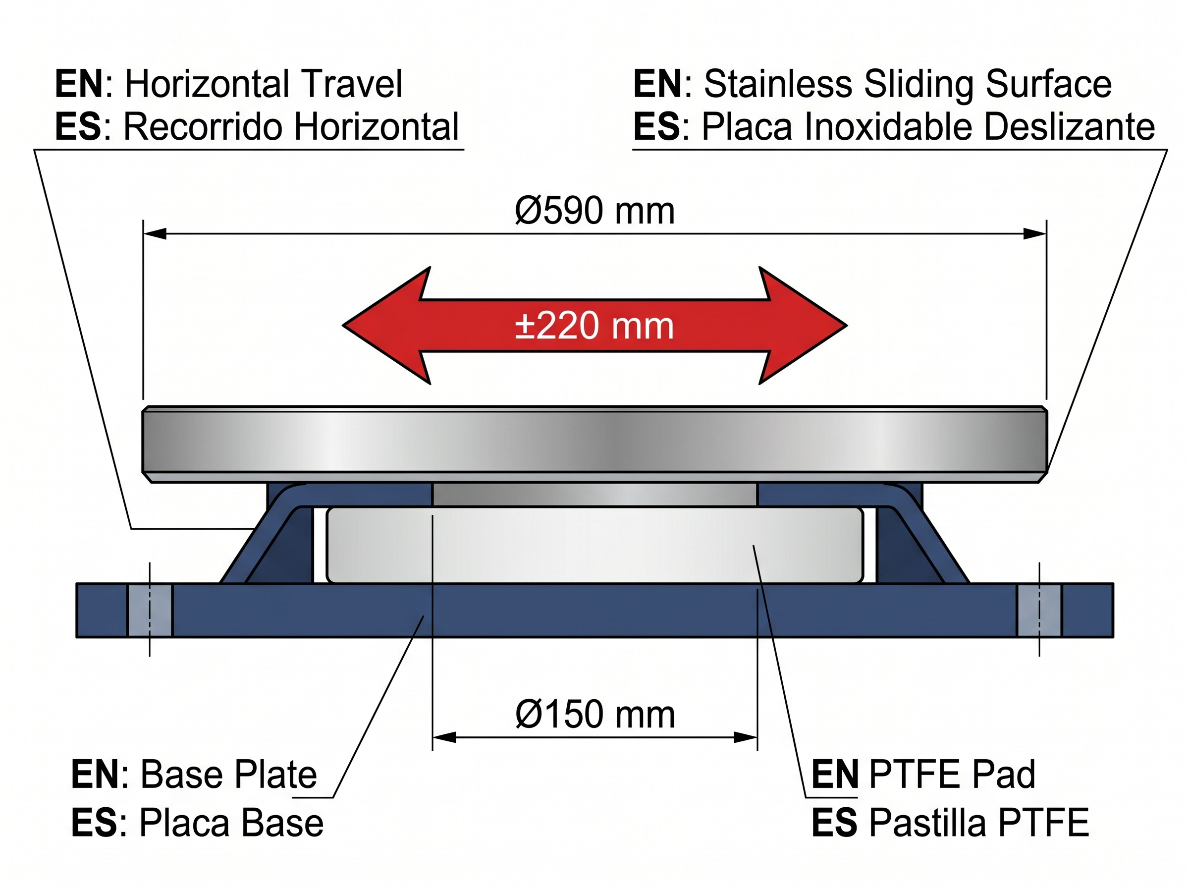
Cada deslizador soporta 50 ton. Su pastilla de PTFE de Ø150 mm trabaja a una presión de 27.7 MPa contra una placa de acero inoxidable de Ø590 mm, con un coeficiente de fricción μ = 0.06 y un recorrido horizontal de ±220 mm, holgado frente al desplazamiento máximo de 22 cm.
Paso 7 — El sistema completo
Las contribuciones individuales se suman para describir el sistema de aislamiento como un todo: rigidez inicial K1 = 65,063 kN/m, rigidez post-fluencia Kd = 6,506 kN/m, fuerza característica Qd = 880 kN y rigidez efectiva Keff = 11,396 kN/m. De ahí salen los números que definen el éxito del diseño:
El periodo del sistema es de 2.57 s y el amortiguamiento efectivo, del 25.8 %, ambos por encima de los objetivos. El resultado es un cortante basal de 2,051 kN y un coeficiente sísmico V/W = 0.110: la estructura solo "siente" un 11 % de su peso como fuerza lateral, una fracción de lo que experimentaría con base fija.
Paso 8 — Las conexiones
El último eslabón son las conexiones que unen cada aislador a la estructura. La placa extrema del aislador es de 3/4" en acero A572-50 y la placa de columna, de 1" en el mismo acero; ambas se unen con 6 pernos de Ø3/4" A307 dispuestos en un círculo de Ø550 mm. Un detalle de diseño importante: el peso del edificio mantiene los pernos permanentemente en compresión, de modo que la conexión no entra en tracción ni siquiera durante el volteo sísmico.
Conclusión
El diseño de los 26 apoyos de la Torre Médica de Bahía de Banderas muestra cómo el aislamiento de base convierte un sitio de altísimo peligro sísmico en una estructura que responde con calma: periodo de 2.57 s, 25.8 % de amortiguamiento y apenas un 11 % del peso como cortante basal.
Los siguientes pasos del proyecto son el análisis tiempo-historia con registros sísmicos representativos del sitio y los ensayos de prototipo de los aisladores conforme a la ASCE 7-22 §17.8, que validan en laboratorio las propiedades supuestas en el cálculo. Cada uno de estos valores —y cada uno de los que aparecen en este artículo— se respalda en su norma correspondiente, fiel al principio que guía cada proyecto de VELATOPH®: cada cálculo cita su norma.
The Specialty Medical Tower of Bahía de Banderas, Nayarit, rises over one of the most demanding seismic environments in Mexico. Off this coast, the Rivera plate and the Jalisco block interact, a tectonic boundary that seismology has identified as a seismic gap: a zone capable of generating earthquakes of magnitude greater than 7 with an estimated recurrence of 40 to 45 years. For a hospital —a facility that must keep operating immediately after the earthquake— resisting is not enough: it must be protected.
Base seismic isolation responds to that demand with a physically simple idea. Instead of making the structure stiffer and stronger so it absorbs the earthquake's energy, a plane of flexible devices is inserted between the foundation and the building, decoupling the superstructure from the ground motion. In doing so, the natural period of the system is deliberately lengthened —from half a second to more than two and a half seconds— and the acceleration reaching the floors drops drastically. The building moves almost as a rigid body over a layer that dissipates the energy.
This article walks, step by step, through how the VELATOPH® engineering team designed this tower's isolation system with the seismic isolation module of Alpha Estructural, its own calculation platform, under the framework of Chapter 17 of ASCE 7-22, the NTC-Sismo CDMX 2023 and the AASHTO Guide Specifications for Seismic Isolation Design.
What an LRB isolator is
The heart of the system is the LRB (Lead-Rubber Bearing, an elastomeric isolator with a lead core). It is a cylinder formed by dozens of thin rubber layers interleaved with steel sheets —the shims—, all confined between two steel plates that connect it to the structure. A solid lead core runs through its center.
Each component fulfills a precise function:
- The rubber layers provide the low horizontal stiffness that lengthens the period: the isolator deforms laterally with ease.
- The steel sheets confine the rubber and prevent it from bulging under the weight of the building, providing enormous vertical stiffness without reducing horizontal flexibility.
- The lead core is the damper: by deforming plastically in each cycle, it converts the earthquake's energy into heat and limits the displacement.
- The end plates transmit the vertical load and anchor the device to the structure.
The behavior of the LRB is described with a bilinear model: very stiff at first —while the lead has not yet yielded— and much more flexible afterward, when the lead yields and the force is governed by the rubber. From that model come three key numbers: the post-yield stiffness (Kd), which sets the flexible slope; the characteristic strength (Qd), which measures how much energy the lead dissipates; and the effective stiffness (Keff), the average that defines the period of the system.
Step 1 — Define the demands
Every design starts from the demands the system must satisfy. For this tower:
- Vertical loads: the isolation plane supports a service weight of 1,902.24 ton. A distinction is made between the service load (permanently present) and the maximum design load (which includes the vertical seismic and overturning effects).
- Displacements: a design displacement DD = 18 cm for sizing, and a maximum displacement DM = 22 cm to verify stability in the extreme earthquake.
- Target period: ≈ 2.5 s, enough to move the structure away from the highest-energy zone of the spectrum.
- Target damping: ≥ 21 %, well above the 5 % of a conventional structure.
Step 2 — The key distinction: service vs. design
Here is the concept that causes the most errors. The period of the system is calculated with the service load, because the mass that actually vibrates during the earthquake is that of the permanent weight. By contrast, the strength and stability are verified with the maximum design load, which is greater because it adds the seismic effects. They are two loads for two different questions: "at what period does it vibrate?" and "does it withstand the worst case?".
Step 3 — Geometric sizing
With the demands clear, the geometry is defined: outer diameter, total rubber thickness, number of layers and lead core diameter. Both models of this tower share an outer diameter of Ø450 mm and 22 rubber layers of 8 mm (total rubber thickness tr = 176 mm), with a total height close to 30 cm. The lead core varies with the load: Ø73 mm in the LRB-1, the most heavily loaded, and Ø65 mm in the LRB-2.
Two shape factors govern the sizing:
- The primary shape factor S1 relates the loaded area to the free area of each rubber layer and controls the vertical stiffness of the isolator.
- The secondary shape factor S2 —here 2.56— relates the diameter to the total rubber thickness and controls the stability against buckling: an isolator that is too slender would buckle under load when displaced.
The choice of rubber is a compromise between period, damping and size. A low shear modulus, G = 0.36 MPa, gives the flexibility needed to reach the target period without resorting to a disproportionately tall device; combined with the lead core (shear yield fyL = 10 MPa), it delivers period and damping in a single compact body.
Step 4 — Dynamic properties
Once the geometry is defined, the dynamic properties of each isolator are calculated. The lead provides the characteristic strength Qd; the confined rubber provides the post-yield stiffness Kd; together they define the effective stiffness Keff, the individual period T and the damping ξ.
The bilinear hysteresis curve sums up the entire behavior: the larger the area enclosed by the loop, the more energy the device dissipates in each loading and unloading cycle. These are the design results for the two models:
| Parameter | LRB-1 (×6) | LRB-2 (×14) |
|---|---|---|
| Service / maximum design load | 87 / 146.5 ton | 78 / 132 ton |
| Outer diameter | Ø450 mm | Ø450 mm |
| Lead core | Ø73 mm | Ø65 mm |
| Rubber layers | 22 × 8 mm (tr = 176 mm) | 22 × 8 mm |
| Total height | ~30 cm | ~30 cm |
| Post-yield stiffness Kd | 325 kN/m | 325 kN/m |
| Characteristic strength Qd | 41.3 kN | 33.2 kN |
| Effective stiffness Keff | 555 kN/m | 510 kN/m |
| Individual period T | 2.49 s | 2.46 s |
| Damping ξ | 24.3 % | 21.6 % |
| Shape factor S2 | 2.56 | 2.56 |
| Buckling SF (max. load) | 2.45 | 2.73 |
Step 5 — Stability verifications
An isolator must not only tune the period: it must keep supporting the building when displaced to the maximum. For that reason, once the dynamic properties are set, stability is verified:
- The vertical pressure on the rubber under the maximum design load, within the allowable limits.
- The shear strain of the rubber at the maximum displacement DM = 22 cm.
- The reduced area: as it displaces, the effective contact area between the plates decreases, and it must remain sufficient to transmit the vertical load.
- The buckling safety factor with the isolator displaced, which comes out to 2.45 in the LRB-1 and 2.73 in the LRB-2 —both with comfortable margin over unity.
Step 6 — The PTFE sliders
Not all bearings carry a lead core. Six of the 26 are flat PTFE sliders. They are combined with the LRBs because they provide vertical load capacity and controlled friction without adding restoring stiffness: they let the LRBs recenter the building, while they support load and dissipate energy through friction. It is an efficient division of tasks.
Each slider supports 50 ton. Its Ø150 mm PTFE pad works at a pressure of 27.7 MPa against a Ø590 mm stainless steel plate, with a friction coefficient μ = 0.06 and a horizontal travel of ±220 mm, generous relative to the maximum displacement of 22 cm.
Step 7 — The complete system
The individual contributions are added up to describe the isolation system as a whole: initial stiffness K1 = 65,063 kN/m, post-yield stiffness Kd = 6,506 kN/m, characteristic strength Qd = 880 kN and effective stiffness Keff = 11,396 kN/m. From there come the numbers that define the success of the design:
The system period is 2.57 s and the effective damping, 25.8 %, both above the targets. The result is a base shear of 2,051 kN and a seismic coefficient V/W = 0.110: the structure only "feels" 11 % of its weight as lateral force, a fraction of what it would experience with a fixed base.
Step 8 — The connections
The last link is the connections that join each isolator to the structure. The isolator's end plate is 3/4" in A572-50 steel and the column plate, 1" in the same steel; both are joined with 6 bolts of Ø3/4" A307 arranged in a Ø550 mm circle. An important design detail: the weight of the building keeps the bolts permanently in compression, so the connection never goes into tension, not even during seismic overturning.
Conclusion
The design of the 26 bearings of the Bahía de Banderas Medical Tower shows how base isolation turns a site of extremely high seismic hazard into a structure that responds calmly: a period of 2.57 s, 25.8 % damping and barely 11 % of the weight as base shear.
The next steps of the project are the time-history analysis with seismic records representative of the site and the prototype tests of the isolators in accordance with ASCE 7-22 §17.8, which validate in the laboratory the properties assumed in the calculation. Each of these values —and every one that appears in this article— is backed by its corresponding standard, true to the principle that guides every VELATOPH® project: every calculation cites its standard.