Un aislador no sale de la fábrica con la rigidez exacta de la memoria de cálculo: varía de una pieza a otra, cambia con la temperatura de servicio y se modifica con los años. La norma no ignora esa dispersión: la convierte en un dato de diseño.
ASCE 7, en su capítulo 17, exige analizar la estructura aislada con dos juegos de propiedades: un límite inferior y uno superior. No es un análisis de sensibilidad opcional ni un margen añadido al final, sino la forma de asegurar que, cualquiera que sea el aislador que se instale y como sea que envejezca, el edificio siga cumpliendo. Un mismo proyecto tiene, así, dos respuestas que deben verificarse.
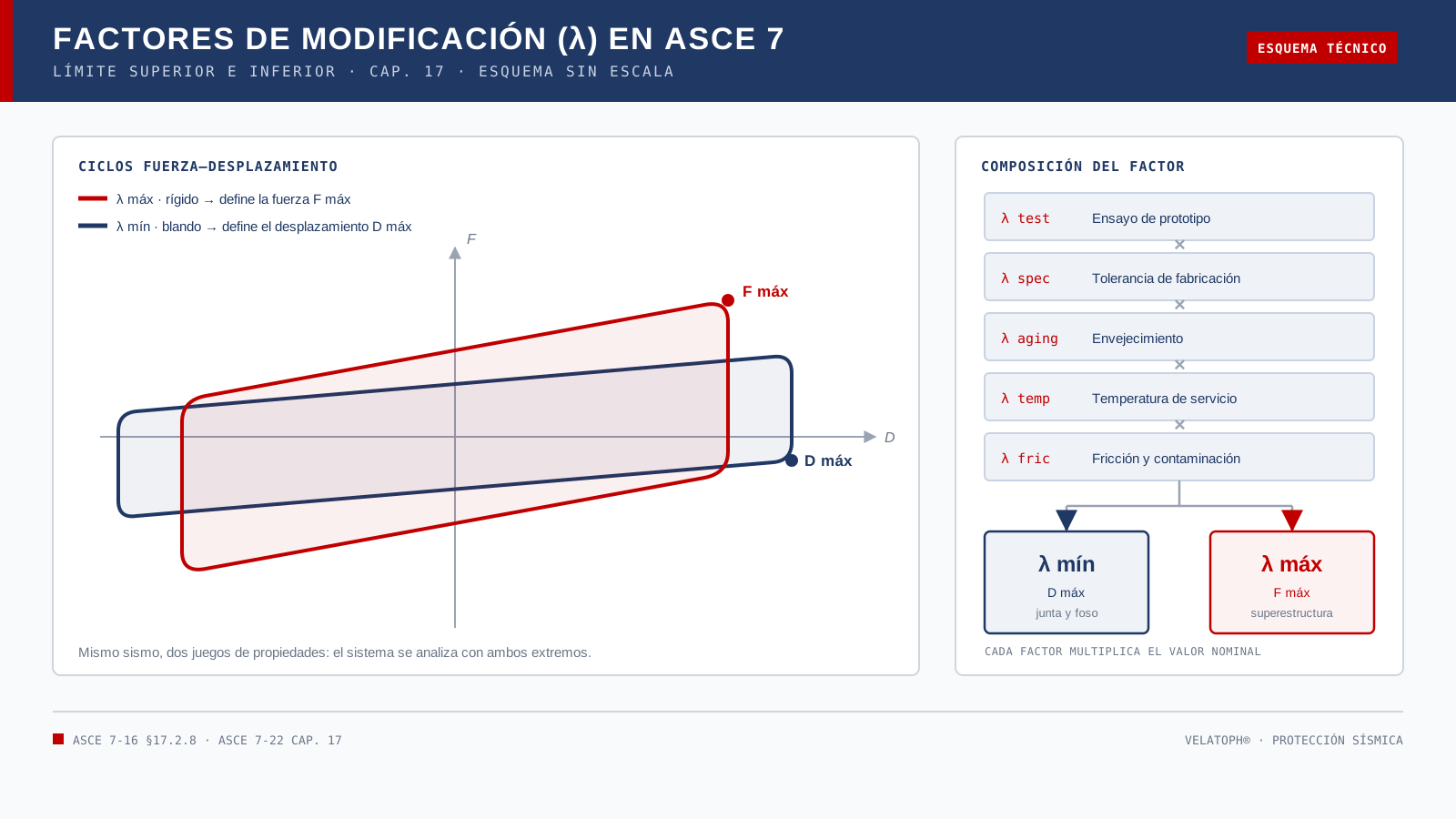
El factor λ, en una línea
Un factor de modificación de propiedades, escrito λ, es un multiplicador que se aplica al valor nominal de una propiedad del aislador: la rigidez efectiva keff, la fuerza característica Qd o el coeficiente de fricción μ. Si el ensayo de prototipo muestra que la rigidez en el primer ciclo puede ser un 12 % mayor que el valor nominal, ese efecto se representa con un factor de 1.12.
Cada fuente de variación aporta su propio factor y los factores se multiplican. El producto da dos números: λmín, que genera el límite inferior, y λmáx, que genera el límite superior. El rango describe lo que el dispositivo puede ser, no lo que se espera que sea.
Cuatro fuentes en un solo producto
La norma no inventa el rango: lo deriva de datos. ASCE 7-16 ordenó estas fuentes en la sección 17.2.8 y ASCE 7-22 conservó el enfoque. Cinco pesan más en la práctica:
| Fuente | Qué la origina | Efecto en el límite |
|---|---|---|
| Ensayo de prototipo λprueba | Diferencia entre el primer y el tercer ciclo: scragging del hule y calentamiento del plomo | El primer ciclo da la fuerza más alta; el tercero, la más baja |
| Especificación λesp | Tolerancias declaradas: dimensiones, dureza y contenido de plomo | Depende del control de producción de cada fábrica |
| Envejecimiento λenvej | Endurecimiento del hule, relajación, oxidación y corrosión | Sube la rigidez con los años; el amortiguamiento puede caer |
| Temperatura λtemp | Temperatura de servicio del elastómero, no la del aire | El frío endurece el compuesto; el calor lo ablanda |
| Fricción y contaminación λfric | Presión, velocidad, polvo, humedad y estado de la superficie | Desplaza la fricción hacia arriba o abajo; en péndulos suele gobernar el rango |
Cuando el fabricante no aporta datos, la norma admite valores por defecto, deliberadamente conservadores: castigan el diseño con un rango más ancho del que tendría un producto caracterizado. Por eso un proveedor que entrega sus factores con respaldo no solo cumple un requisito formal: evita dimensionar con la envolvente más desfavorable posible.
Cómo se combinan
Los factores no se suman ni se promedian: se multiplican. El producto aplicado al valor nominal produce una de las dos fronteras. Un factor mayor que 1 empuja hacia arriba; uno menor que 1, hacia abajo. La misma propiedad puede tener un factor de 1.10 por envejecimiento y otro de 0.90 por temperatura, y el producto resultante es el que entra al análisis.
La guía de McVitty y Constantinou para MCEER, escrita para aplicar estas disposiciones, añade un matiz: no todos los aisladores de una estructura alcanzan el extremo del rango al mismo tiempo. Ese es el concepto de factor de sistema, que reconoce una simultaneidad poco probable en una planta con decenas de dispositivos. Está en la base del enfoque de la norma; usarlo como descuento automático, sin justificación, es un error frecuente.
Por qué bajar la rigidez agranda el desplazamiento
La relación no es intuitiva y conviene verla. En la zona de periodos largos, donde suele quedar un edificio aislado, el desplazamiento crece con el periodo: D ≈ Sv·T/(2π). Si la rigidez baja, el periodo sube y el desplazamiento también. La fuerza se comporta al revés: como V = k·D, y sustituyendo el periodo, V = Sv·√(k·m). Más rigidez, más fuerza transmitida.
En un LRB hay un segundo efecto en la misma dirección. El límite inferior no solo reduce la rigidez posfluencia: también reduce la fuerza característica del núcleo de plomo y, con ella, el amortiguamiento efectivo que entra al cálculo del desplazamiento. Menos amortiguamiento es, otra vez, más desplazamiento. Por eso el límite inferior dimensiona el foso y la junta, y el superior la estructura.
Dos análisis, dos preguntas
ASCE 7 pide verificar el sistema con ambos extremos, y cada uno responde una pregunta distinta:
- Con el límite inferior: ¿cuánto se mueve? Desplazamiento máximo total con amplificación por torsión; holgura de junta y foso; recorrido en tuberías, escaleras y cables; estabilidad al levantamiento y carga axial mínima.
- Con el límite superior: ¿cuánta fuerza llega? Cortante en la interfaz, diafragma y elementos por encima del plano; cimentación, anclajes y elementos por debajo; estabilidad con compresión y desplazamiento simultáneos.
Hay una sutileza que se pasa por alto: la fuerza no se toma solo del límite superior. La norma pide calcular el cortante con ambos juegos y quedarse con la condición que gobierna, porque en periodos cortos el límite inferior puede producir fuerzas mayores. Es un caso poco frecuente, pero existe y un solo análisis no lo detecta.
Elastómero y péndulo no se acotan igual
En un elastómero el rango se concentra en keff y en Qd. El scragging —el ablandamiento inicial del hule virgen— hace que el primer ciclo sea el más alto y el tercero el más bajo, y de ahí sale buena parte del factor de ensayo. La temperatura y el envejecimiento endurecen el compuesto, y su efecto combinado puede ser más severo que cada uno por separado.
En un péndulo de fricción el periodo lo fija el radio de curvatura, no la masa, así que la incertidumbre se concentra en el coeficiente de fricción: un valor bajo da más desplazamiento; uno alto, más fuerza. La superficie deslizante es el punto crítico, y por eso los factores de fricción y de desgaste por recorrido acumulado pesan aquí más que en un elastómero.
Errores que se ven en revisión
Al revisar proyectos aislados, estos son los errores que más se repiten:
- Analizar una sola vez, con las propiedades nominales, y llamarlo diseño.
- Tomar los factores de un catálogo o de otro proyecto: dependen del compuesto, del tamaño y del proceso de cada fábrica.
- Usar el límite inferior para todo «por ser conservador». Para fuerza es lo contrario de conservador.
- Olvidar la torsión al combinar el límite inferior: el desplazamiento total no es el del análisis sin excentricidad.
- Cambiar de dispositivo a mitad del proyecto y no volver a revisar foso, junta, holguras y anclajes.
- No revisar la estabilidad del aislador con compresión y desplazamiento máximos actuando a la vez.
Qué documentar
Un expediente de aislamiento defendible incluye, como mínimo:
- Propiedades nominales con su base: ensayo de origen, temperatura, deformación y velocidad de referencia.
- Reporte de ensayo de prototipo del tipo y del tamaño del proyecto, no de un producto «equivalente».
- Cada factor con su fuente: ensayo, especificación, envejecimiento, temperatura y fricción.
- Los dos modelos y sus resultados: desplazamiento total con el límite inferior y fuerza de diseño con el superior.
- La decisión explícita de qué condición gobierna cada elemento.
Esa documentación permite que un revisor independiente reconstruya el diseño y sepa qué pasaría si el aislador real cae en el otro extremo del rango.
En VELATOPH®
VELATOPH® fabrica en Manzanillo, Colima, aisladores elastoméricos LRB y LDRB, aisladores pendulares FPS y DFP, y disipadores DEF y DVF. En cada proyecto el punto de partida es la carga real por apoyo, la geometría de la estructura y el desplazamiento requerido; las propiedades se entregan con sus límites, no como un número único.
Si estás revisando un proyecto con aislamiento o comparando alternativas, ofrecemos una evaluación técnica gratuita por WhatsApp. También puedes consultar la nota sobre pruebas de prototipo y de producción, el análisis del desplazamiento máximo y la guía para elegir proveedor.
Fuentes
- ASCE. ASCE/SEI 7-22, capítulo 17 y sección 17.2.8 (propiedades límite y factores de modificación). asce.org
- McVitty, W. J. y Constantinou, M. C. Property Modification Factors for Seismic Isolators: Design Guidance for Buildings, MCEER-15-0005, University at Buffalo, 2015. eng.buffalo.edu
- MCEER. Ficha del reporte MCEER-15-0005 (resumen y alcance). buffalo.edu
- FEMA. 2020 NEHRP Recommended Seismic Provisions for New Buildings and Other Structures. fema.gov
- ISO. ISO 22762-1:2024, Elastomeric seismic-protection isolators — Part 1: Test methods. iso.org
Artículo de carácter general y educativo; no sustituye el diseño ni la revisión de un ingeniero responsable de cada proyecto, ni las indicaciones de la autoridad competente.
An isolator does not leave the factory with the exact stiffness shown in the design report: it varies from unit to unit, changes with service temperature and shifts over the years. The standard does not ignore that scatter: it turns it into a design input.
ASCE 7, in Chapter 17, requires the isolated structure to be analyzed with two sets of properties: a lower bound and an upper bound. This is not an optional sensitivity study or a margin added at the end, but the way to ensure that, whatever isolator is installed and however it ages, the building still performs. One project therefore has two answers, and both must be checked.
The λ factor, in one line
A property modification factor, written λ, is a multiplier applied to the nominal value of an isolator property: effective stiffness keff, characteristic strength Qd or friction coefficient μ. If the prototype test shows that first-cycle stiffness may be 12% above the nominal value, that effect is represented by a factor of 1.12.
Each source of variation contributes its own factor, and the factors are multiplied. The product yields two numbers: λmin, which produces the lower bound, and λmax, which produces the upper bound. The range describes what the device can be, not what it is expected to be.
Four sources in a single product
The standard does not invent the range: it derives it from data. ASCE 7-16 organized these sources in Section 17.2.8 and ASCE 7-22 kept the approach. Five of them dominate in practice:
| Source | What causes it | Effect on the bound |
|---|---|---|
| Prototype test λtest | Difference between the first and third cycle: rubber scragging and lead heating | The first cycle gives the highest force; the third, the lowest |
| Specification λspec | Declared tolerances: dimensions, hardness and lead content | Depends on each factory's production control |
| Aging λaging | Rubber hardening, relaxation, oxidation and corrosion | Stiffness rises with age; damping may drop |
| Temperature λtemp | Service temperature of the elastomer, not the air temperature | Cold stiffens the compound; heat softens it |
| Friction and contamination λfric | Pressure, velocity, dust, moisture and surface condition | Moves friction up or down; in pendulum bearings it often governs the range |
When the manufacturer provides no data, the standard allows default values, deliberately conservative: they penalize the design with a wider range than a characterized product would have. That is why a supplier who delivers its factors with supporting data is not just meeting a formal requirement: it avoids sizing with the most unfavorable envelope possible.
How they combine
The factors are not added or averaged: they are multiplied. The product applied to the nominal value produces one of the two boundaries. A factor above 1 pushes up; one below 1 pushes down. The same property may have a factor of 1.10 for aging and another of 0.90 for temperature, and the resulting product is what enters the analysis.
The McVitty and Constantinou guidance for MCEER, written to apply these provisions, adds a nuance: not every isolator in a structure reaches the extreme of the range at the same time. That is the concept of a system factor, which acknowledges an unlikely simultaneity in a plan with dozens of devices. It underlies the standard's approach; using it as an automatic discount, without justification, is a common mistake.
Why lower stiffness means larger displacement
The relationship is not intuitive, so it is worth seeing. In the long-period range, where an isolated building usually sits, displacement grows with period: D ≈ Sv·T/(2π). If stiffness drops, the period rises and so does displacement. Force behaves the other way: since V = k·D, and substituting the period, V = Sv·√(k·m). More stiffness, more transmitted force.
In an LRB there is a second effect in the same direction. The lower bound does not only reduce post-yield stiffness: it also reduces the lead core's characteristic strength and, with it, the effective damping that enters the displacement calculation. Less damping is, again, more displacement. That is why the lower bound sizes the moat and the joint, while the upper bound sizes the structure.
Two analyses, two questions
ASCE 7 requires the system to be checked with both extremes, and each answers a different question:
- With the lower bound: how far does it move? Total maximum displacement with torsional amplification; joint and moat clearance; travel in piping, stairs and cables; uplift stability and minimum axial load.
- With the upper bound: how much force arrives? Shear at the interface, diaphragm and elements above the plane; foundation, anchorage and elements below; stability under simultaneous compression and displacement.
One subtlety is often overlooked: force is not taken from the upper bound alone. The standard requires base shear to be computed with both sets and the governing condition to be used, because at short periods the lower bound can produce larger forces. It is an uncommon case, but it exists and a single analysis will not detect it.
Elastomer and pendulum are not bounded alike
In an elastomer the range concentrates on keff and Qd. Scragging —the initial softening of virgin rubber— makes the first cycle the highest and the third the lowest, and much of the test factor comes from there. Temperature and aging stiffen the compound, and their combined effect can be more severe than either one alone.
In a friction pendulum the period is set by the radius of curvature, not by mass, so uncertainty concentrates on the friction coefficient: a low value gives more displacement; a high one, more force. The sliding surface is the critical point, which is why friction and cumulative-travel factors matter here more than in an elastomer.
Mistakes seen in review
When reviewing isolated projects, these are the most frequent mistakes:
- Analyzing once, with nominal properties, and calling it design.
- Taking the factors from a catalog or from another project: they depend on each factory's compound, size and process.
- Using the lower bound for everything “to be conservative.” For force it is the opposite of conservative.
- Forgetting torsion when combining the lower bound: total displacement is not the value from an analysis without eccentricity.
- Changing the device mid-project and not rechecking the moat, joint, clearances and anchorage.
- Not checking device stability with maximum compression and maximum displacement acting together.
What to document
A defensible isolation file includes, at a minimum:
- Nominal properties with their basis: source test, temperature, strain and reference velocity.
- A prototype test report for the type and size used in the project, not for an “equivalent” product.
- Each factor with its source: test, specification, aging, temperature and friction.
- Both models and their results: total displacement with the lower bound and design force with the upper bound.
- An explicit decision on which condition governs each element.
That documentation lets an independent reviewer reconstruct the design and know what would happen if the actual isolator fell at the other end of the range.
At VELATOPH®
VELATOPH® manufactures in Manzanillo, Colima, LRB and LDRB elastomeric isolators, FPS and DFP pendulum isolators, and DEF and DVF dampers. In every project the starting point is the actual load per bearing, the geometry of the structure and the required displacement; properties are delivered with their bounds, not as a single number.
If you are reviewing an isolated project or comparing alternatives, we offer a free technical assessment via WhatsApp. You can also read the note on prototype and production testing, the analysis of maximum displacement and the guide to choosing a supplier.
Sources
- ASCE. ASCE/SEI 7-22, Chapter 17 and Section 17.2.8 (bounded properties and modification factors). asce.org
- McVitty, W. J. and Constantinou, M. C. Property Modification Factors for Seismic Isolators: Design Guidance for Buildings, MCEER-15-0005, University at Buffalo, 2015. eng.buffalo.edu
- MCEER. MCEER-15-0005 report record (abstract and scope). buffalo.edu
- FEMA. 2020 NEHRP Recommended Seismic Provisions for New Buildings and Other Structures. fema.gov
- ISO. ISO 22762-1:2024, Elastomeric seismic-protection isolators — Part 1: Test methods. iso.org
General, educational article; it does not replace the design or review by an engineer responsible for each project, or the instructions of the competent authority.