Un edificio aislado sólo funciona si puede moverse. Todo el beneficio del aislamiento sísmico —menos aceleración en los pisos, menos daño en la estructura y en los contenidos— se paga con un desplazamiento grande en la base, que en sismos fuertes puede llegar a decenas de centímetros. Ese movimiento necesita un espacio libre alrededor del edificio: la junta de separación, que en sótanos y plantas de aislamiento suele tomar la forma de un foso perimetral (en inglés, moat). Es una de las partes más sencillas del sistema y, al mismo tiempo, una de las que más fácil se arruinan en obra.
Qué es el foso y para qué sirve
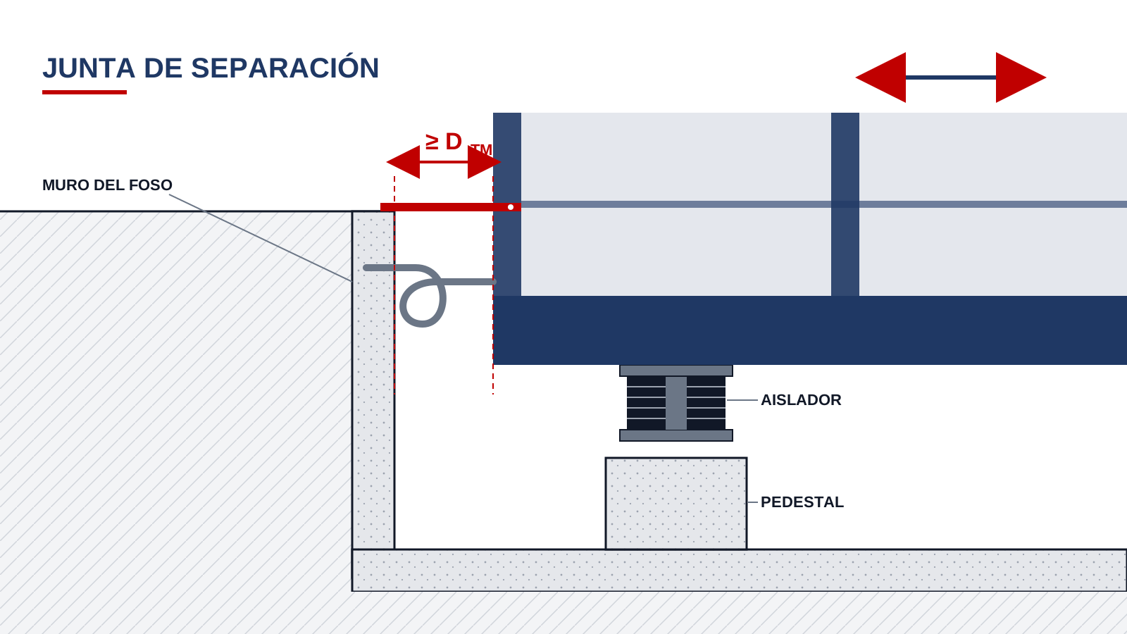
El foso es el hueco que queda entre la losa de aislamiento (la que se apoya sobre los aisladores) y todo lo que está fijo al terreno: muros de contención, banquetas, rampas, edificios vecinos. Su ancho debe ser suficiente para que, en el sismo máximo considerado, la superestructura se desplace sin tocar nada. Si la junta se cierra, el edificio deja de estar “aislado” justo en el momento crítico: golpea contra el muro y la energía que debía absorber el aislador regresa a la estructura en forma de impacto.
Cuánto debe medir: qué pide ASCE 7
El capítulo 17 de ASCE 7-22 establece que la separación mínima entre la estructura aislada y los muros de contención u otras obstrucciones fijas no debe ser menor que el desplazamiento máximo total DTM (sección 17.2.5.2). Hay tres detalles que conviene tener claros:
- Es el sismo máximo, no el de diseño. DTM se calcula con el sismo máximo considerado (MCER), aunque la superestructura se diseñe con fuerzas reducidas. Por eso el foso suele ser más ancho de lo que el arquitecto espera.
- Incluye la torsión. DTM parte del desplazamiento del centro de masa, DM, y le suma el efecto de la torsión real y accidental; las esquinas del edificio se mueven más que el centro. La norma fija como mínimo DTM = 1.15·DM.
- Usa las propiedades extremas. El desplazamiento máximo sale del análisis con el límite inferior de las propiedades del aislador (menor rigidez y amortiguamiento), que es el caso que más desplaza.
Como orden de magnitud, en el ejemplo ilustrativo de nuestro artículo sobre el espectro de diseño el desplazamiento resultó DM ≈ 0.37 m; con el mínimo de torsión, DTM ≥ 0.43 m. Es decir, más de 40 cm libres en todo el perímetro, sin contar tolerancias de construcción.
En México, las NTC para Diseño por Sismo de la Ciudad de México y el Manual de Diseño de Obras Civiles de CFE tienen sus propios requisitos para estructuras aisladas; el criterio de fondo es el mismo: la holgura se dimensiona con el desplazamiento máximo del sistema de aislamiento.
Qué pasa si el edificio golpea el muro
El golpeteo contra el muro del foso no es un riesgo teórico. Masroor y Mosqueda (MCEER, 2013) recopilan dos casos documentados: el edificio aislado del centro de mando de bomberos de Los Ángeles golpeó su muro de foso durante el sismo de Northridge de 1994, lo que aumentó el cortante y las derivas de la estructura, y en el sismo de Christchurch de 2011 hubo evidencia de golpeteo en el único edificio aislado de la zona de movimiento fuerte, con daño en los elementos no estructurales “de sacrificio” de la junta.
En sus ensayos en mesa vibradora, los mismos autores encontraron que las fuerzas de contacto pueden provocar fluencia en la superestructura y amplificar las aceleraciones en todos los niveles. Sus estudios de colapso concluyeron que la holgura exigida por la norma daba una probabilidad de colapso aceptable para los marcos a momento estudiados, pero el modelo con contraventeos necesitó una junta 17 % más ancha para lograrlo. En Japón, Nakazawa y colaboradores (15WCEE, 2012) señalan que muchos ingenieros eligen holguras de dos o tres veces el desplazamiento calculado, precisamente por la incertidumbre de los sismos extremos.
Errores comunes de obra
La mayoría de los problemas no vienen del cálculo, sino de decisiones pequeñas durante la construcción o, años después, durante el uso del inmueble:
| Error | Por qué es grave | Cómo evitarlo |
|---|---|---|
| Cimbra, escombro o relleno dentro del foso | Bloquea el desplazamiento de forma rígida e invisible | Inspección del foso libre antes de entregar y en cada mantenimiento |
| Muro fuera de plomo o recrecido | Reduce la holgura en zonas puntuales | Medir la junta construida y sumar tolerancia al ancho de proyecto |
| Cubrejunta fijada en ambos lados | Convierte la tapa en un puntal entre edificio y terreno | Fijarla de un solo lado y que deslice o se desprenda sin trabar |
| Tuberías rígidas que cruzan la junta | Se rompen (agua, gas, drenaje) o restringen el movimiento | Conexiones flexibles diseñadas para DTM en todas direcciones |
| Escaleras, rampas o fosos de elevador ligados al terreno | Crean un “ancla” que atraviesa el plano de aislamiento | Colgar los elementos del lado aislado o separarlos con su propia holgura |
| Obras posteriores: banquetas, jardineras, ampliaciones | Se cuelan contra la estructura sin saber que hay una junta | Señalizar la junta y dejarla registrada en el manual de operación |
También hay que revisar la holgura vertical. Los aisladores de péndulo (FPS, DFP) levantan ligeramente la estructura al desplazarse sobre su superficie curva, y debajo de la losa de aislamiento no debe haber nada que estorbe ese recorrido.
Lista de revisión antes de entregar la obra
- Ancho de junta medido en todo el perímetro, esquinas incluidas, contra el DTM del proyecto.
- Foso limpio: sin cimbra, sin escombro, sin material almacenado.
- Cubrejuntas y sellos con un solo lado fijo; nada que trabe el movimiento.
- Cada instalación que cruza la junta, con su tramo flexible y la holgura indicada por el fabricante.
- Escaleras, rampas, elevadores y muros divisorios revisados para que no conecten la superestructura con el terreno.
- Acceso para inspeccionar el foso y los aisladores, y la junta marcada en planos “como se construyó” y en el manual de mantenimiento.
En VELATOPH®
VELATOPH® fabrica en Manzanillo, Colima, aisladores elastoméricos LRB y LDRB, aisladores de péndulo FPS y DFP y disipadores DEF y DVF, y trabaja con la normativa ASCE 7-22 (capítulos 17 y 18), AASHTO LRFD, ISO 22762, NTC-CDMX 2023 y CFE-Sismo 2015.
Si estás proyectando un edificio aislado y quieres revisar el desplazamiento de diseño, el ancho del foso o los detalles de la junta, te ofrecemos una evaluación técnica gratuita. Escríbenos por WhatsApp.
Fuentes
- ASCE/SEI 7-22, Minimum Design Loads and Associated Criteria for Buildings and Other Structures, capítulo 17 (secciones 17.2.5.2 y 17.5.3). asce.org
- Masroor, A. y Mosqueda, G. (2013). Seismic Response of Base Isolated Buildings Considering Pounding to Moat Walls. Reporte técnico MCEER-13-0003, University at Buffalo. buffalo.edu
- Nakazawa, T., Kishiki, S., Qu, Z. y Wada, A. (2012). Safety Margin Ratio-Based Design of Isolation Gap Size for Base-isolated Structures. 15th World Conference on Earthquake Engineering, Lisboa. iitk.ac.in
- STRUCTURE magazine. Minding the Gap: Design of Seismic Separations. structuremag.org
An isolated building only works if it can move. The whole benefit of seismic isolation —lower floor accelerations, less damage to the structure and its contents— is paid for with a large displacement at the base, which in strong earthquakes can reach tens of centimeters. That movement needs free space around the building: the separation joint, which in basements and isolation levels usually takes the form of a perimeter moat. It is one of the simplest parts of the system and, at the same time, one of the easiest to ruin on site.
What the moat is and what it is for
The moat is the gap left between the isolation slab (the one resting on the isolators) and everything fixed to the ground: retaining walls, sidewalks, ramps, neighboring buildings. Its width must be enough for the superstructure to move under the maximum considered earthquake without touching anything. If the joint closes, the building stops being “isolated” right at the critical moment: it strikes the wall, and the energy the isolator was meant to absorb returns to the structure as an impact.
How wide it must be: what ASCE 7 requires
Chapter 17 of ASCE 7-22 states that the minimum separation between the isolated structure and retaining walls or other fixed obstructions shall not be less than the total maximum displacement DTM (Section 17.2.5.2). Three details are worth keeping clear:
- It is the maximum earthquake, not the design earthquake. DTM is computed with the maximum considered earthquake (MCER), even though the superstructure is designed for reduced forces. That is why the moat is usually wider than the architect expects.
- It includes torsion. DTM starts from the center-of-mass displacement, DM, and adds the effect of inherent and accidental torsion; the building's corners move more than its center. The standard sets a minimum of DTM = 1.15·DM.
- It uses the bounding properties. The maximum displacement comes from the analysis with the isolator's lower-bound properties (lower stiffness and damping), which is the case that displaces the most.
As an order of magnitude, in the illustrative example in our article on the design spectrum the displacement was DM ≈ 0.37 m; with the torsion minimum, DTM ≥ 0.43 m. That is, more than 40 cm of clearance around the entire perimeter, before construction tolerances.
In Mexico, the Mexico City NTC for Seismic Design and the CFE Civil Works Design Manual have their own requirements for isolated structures; the underlying criterion is the same: the clearance is sized with the isolation system's maximum displacement.
What happens if the building strikes the wall
Pounding against the moat wall is not a theoretical risk. Masroor and Mosqueda (MCEER, 2013) document two cases: the isolated Fire Command and Control building in Los Angeles struck its moat wall during the 1994 Northridge earthquake, which increased the structure's shear and drift demands, and in the 2011 Christchurch earthquake there was evidence of pounding in the only isolated building in the strong-shaking region, with damage to the “sacrificial” nonstructural components at the joint.
In their shake-table tests, the same authors found that contact forces can cause yielding in the superstructure and amplify accelerations at every level. Their collapse studies concluded that the code-required clearance gave an acceptable collapse probability for the moment frames studied, but the braced-frame model needed a joint 17% wider to achieve it. In Japan, Nakazawa and colleagues (15WCEE, 2012) note that many engineers choose clearances of two or three times the computed displacement, precisely because of the uncertainty of extreme earthquakes.
Common construction errors
Most problems do not come from the calculations, but from small decisions during construction or, years later, during the building's use:
| Error | Why it is serious | How to avoid it |
|---|---|---|
| Formwork, debris or fill inside the moat | Blocks displacement rigidly and invisibly | Inspect the moat for clearance before handover and at every maintenance visit |
| Wall out of plumb or thickened | Reduces clearance at specific points | Measure the as-built joint and add tolerance to the design width |
| Joint cover fixed on both sides | Turns the cover into a strut between building and ground | Fix it on one side only so it slides or detaches without jamming |
| Rigid pipes crossing the joint | They break (water, gas, drainage) or restrain movement | Flexible connections designed for DTM in every direction |
| Stairs, ramps or elevator pits tied to the ground | They create an “anchor” across the isolation plane | Hang the elements from the isolated side or separate them with their own clearance |
| Later works: sidewalks, planters, extensions | Cast against the structure without knowing there is a joint | Mark the joint and record it in the operations manual |
The vertical clearance must also be checked. Pendulum isolators (FPS, DFP) lift the structure slightly as they slide along their curved surface, and nothing beneath the isolation slab should obstruct that travel.
Checklist before handing over the building
- Joint width measured around the entire perimeter, corners included, against the project's DTM.
- Clean moat: no formwork, no debris, no stored material.
- Joint covers and seals with one side fixed only; nothing that jams the movement.
- Every utility crossing the joint with its flexible segment and the clearance specified by the manufacturer.
- Stairs, ramps, elevators and partition walls checked so that none connects the superstructure to the ground.
- Access to inspect the moat and the isolators, and the joint marked on as-built drawings and in the maintenance manual.
At VELATOPH®
VELATOPH® manufactures in Manzanillo, Colima, LRB and LDRB elastomeric isolators, FPS and DFP pendulum isolators and DEF and DVF dampers, and works with the ASCE 7-22 (Chapters 17 and 18), AASHTO LRFD, ISO 22762, NTC-CDMX 2023 and CFE-Sismo 2015 standards.
If you are designing an isolated building and want to review the design displacement, the moat width or the joint details, we offer a free technical assessment. Write to us on WhatsApp.
Sources
- ASCE/SEI 7-22, Minimum Design Loads and Associated Criteria for Buildings and Other Structures, Chapter 17 (Sections 17.2.5.2 and 17.5.3). asce.org
- Masroor, A. and Mosqueda, G. (2013). Seismic Response of Base Isolated Buildings Considering Pounding to Moat Walls. Technical Report MCEER-13-0003, University at Buffalo. buffalo.edu
- Nakazawa, T., Kishiki, S., Qu, Z. and Wada, A. (2012). Safety Margin Ratio-Based Design of Isolation Gap Size for Base-isolated Structures. 15th World Conference on Earthquake Engineering, Lisbon. iitk.ac.in
- STRUCTURE magazine. Minding the Gap: Design of Seismic Separations. structuremag.org