Un disipador viscoso no se elige por catálogo como se elige una tubería. Su fuerza depende de la velocidad a la que se mueve, y esa relación —no la apariencia del equipo— es la que el modelo estructural supuso. Por eso el ensayo no es un trámite de entrega: es la única evidencia de que el dispositivo instalado se comporta como el que se analizó.
En el análisis, el amortiguador entra como una ley F = C·Vα. Si el coeficiente C real resulta un 20% mayor que el supuesto, la conexión y el marco se sobrecargan; si resulta menor, la deriva no baja lo que prometió el estudio. El ensayo cierra esa brecha entre el modelo y el producto.
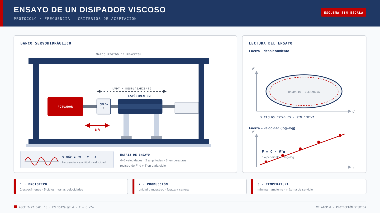
Qué se verifica en un disipador viscoso
Un protocolo completo no se limita a mover el pistón y mirar la gráfica. Verifica, como mínimo:
- La ley fuerza-velocidad en todo el rango creíble, no sólo en el punto de diseño.
- La carrera útil y el comportamiento en los extremos, sin topes prematuros ni agarrotamiento.
- La estanqueidad del cilindro y la integridad de sellos bajo presión.
- La estabilidad térmica de la fuerza, porque la viscosidad del fluido cambia con la temperatura.
- La energía acumulada que puede disipar sin sobrecalentarse y su vida cíclica.
La frecuencia es otra forma de decir velocidad
En un ensayo sinusoidal, la velocidad pico no depende sólo de la frecuencia: depende también de la amplitud. La relación es vmáx = 2π·f·A, con A medida de cero a pico. Duplicar la frecuencia duplica la velocidad; duplicar la carrera hace lo mismo. Por eso un protocolo que fija «ensayar a 1 Hz» sin decir la amplitud no dice nada útil.
| Amplitud A (mm) | Frecuencia f (Hz) | Velocidad pico (m/s) |
|---|---|---|
| 50 | 0.5 | 0.16 |
| 100 | 0.5 | 0.31 |
| 100 | 1.0 | 0.63 |
| 200 | 0.5 | 0.63 |
| 200 | 1.0 | 1.26 |
Si el rango de diseño del proyecto va de 0.1 a 1.0 m/s, el ensayo tiene que cubrir esa ventana con varios puntos. Un solo punto no permite identificar C y α: con dos incógnitas hace falta un ajuste, y un ajuste necesita al menos cuatro o cinco velocidades. En la práctica se ensaya al 20%, 40%, 60%, 80% y 100% de la velocidad máxima, y se ajusta la ley potencial sobre esos pares de fuerza y velocidad.
Ensayo de tipo: caracterizar antes de fabricar
El ensayo de tipo —o de prototipo— se hace sobre ejemplares de tamaño real antes de fabricar la serie. Es el que define C, α y la envolvente de comportamiento del producto.
ASCE 7-22, en su capítulo 18, parte de un mínimo de dos especímenes de tamaño completo y somete el dispositivo a ciclos repetidos a desplazamiento de diseño y a desplazamiento máximo, además de las pruebas que caracterizan la dependencia con la velocidad. EN 15129 sigue una lógica equivalente para dispositivos dependientes de la velocidad: ensayo de tipo para fijar las propiedades de cálculo y control de la producción en fábrica de la serie.
En la práctica, el programa suele incluir:
- Barrido de velocidades para ajustar la ley potencial.
- Ciclos repetidos a desplazamiento de diseño y a desplazamiento máximo, con registro de fuerza y desplazamiento en cada ciclo.
- Repetición a temperatura mínima, ambiente y máxima de servicio.
- Prueba de presión —del orden de 1.25 veces la máxima de servicio, sostenida— y verificación de fugas.
- Energía acumulada y vida cíclica, según el uso: sísmico, viento o tráfico.
- Inspección posterior: sellos, vástago, deformación residual y funcionamiento.
Ensayo de producción: verificar lo que sale del taller
El ensayo de tipo califica el diseño; el de producción verifica cada unidad. ASCE 7-22 exige pruebas de producción y tolerancias sobre la fuerza; EN 15129 las agrupa en el control de producción en fábrica. Lo habitual es ensayar cada dispositivo a la velocidad de diseño y a su carrera nominal, y complementar con muestreo cuando el volumen es alto.
El punto crítico no es el número de ensayos, sino la trazabilidad: número de serie, fecha, laboratorio, instrumentos calibrados, temperatura ambiente y curvas crudas. Un certificado sin esos datos no permite reconstruir nada.
Criterios de aceptación
Los valores exactos quedan fijados por la especificación del proyecto y la norma aplicable; la tabla siguiente resume los criterios que suelen fijarse. Ninguno se acepta «a ojo»: cada uno compara una medición contra un número escrito antes del ensayo.
| Verificación | Qué se mide | Criterio habitual |
|---|---|---|
| Fuerza a velocidad de diseño | Fuerza pico en el ciclo | ±10% a ±15% del valor declarado |
| Ley fuerza-velocidad | Ajuste de C y α con 4–5 puntos | Dispersión dentro de la banda del proyecto |
| Estabilidad cíclica | Variación de la fuerza entre ciclos | Sin deriva monotónica; variación acotada |
| Estanqueidad | Fuga visible y caída de presión | Sin fuga tras la prueba de presión |
| Carrera | Recorrido completo | Sin agarrotamiento ni topes prematuros |
| Temperatura | Fuerza a temperatura mínima, ambiente y máxima | Dentro de la envolvente declarada |
Los errores que invalidan un ensayo
La mayoría de los resultados que no resisten una revisión independiente fallan por la misma lista corta:
- Ensayar sólo a baja frecuencia y llamarlo «cuasi-estático».
- No estabilizar la temperatura del fluido antes de medir.
- Medir el desplazamiento con el sensor interno del actuador y no con un transductor independiente.
- Ignorar la flexibilidad del marco y de las conexiones: parte del desplazamiento se va en la estructura de prueba.
- Escalar un prototipo sin semejanza hidráulica y presentar el resultado como si fuera el dispositivo real.
- Reportar una curva sin C, α, temperatura, calibración ni número de serie.
Qué debe contener el informe
Un informe que sirva para revisión y para expediente de obra incluye, como mínimo:
- Identificación del espécimen y del proyecto.
- Laboratorio, fecha y norma aplicada.
- Instrumentación y certificados de calibración.
- Matriz de ensayo: amplitud, frecuencia, velocidad, temperatura y número de ciclos.
- Datos crudos y curvas fuerza-desplazamiento.
- Ajuste de C y α con su dispersión.
- Comparación contra la tolerancia del proyecto y dictamen.
- Firmas y registro fotográfico.
Dónde encaja la normativa mexicana
En México, la demanda sísmica de diseño sale de las normas técnicas complementarias y de CFE-Sismo; el diseño del amortiguamiento se apoya en ASCE 7-22 y, para puentes, en AASHTO. Las NTC-CDMX fijan criterios de diseño y revisión, pero no sustituyen el protocolo de ensayo del fabricante. ISO 22762, que sí se cita para aisladores elastoméricos, no aplica a disipadores viscosos: es una norma de aisladores, no de amortiguadores.
Por eso la revisión independiente —la que ASCE 7 prevé para sistemas de amortiguamiento— mira tres cosas: la ley declarada, el ensayo que la respalda y la tolerancia con la que se aceptó. Si falta una de las tres, el expediente queda incompleto aunque el dispositivo funcione.
En VELATOPH®
VELATOPH® fabrica en Manzanillo, Colima, disipadores de fluido viscoso DVF con fuerza de diseño de 100 a 20,000 kN, velocidad de 0.05 a 1.5 m/s, exponente α de 0.3 a 1.0 y carrera de ±5 a ±100 cm; el fluido es silicona inerte y el rango de servicio va de −40 °C a +80 °C. Los dispositivos se especifican según la demanda del proyecto y se documentan con el protocolo de ensayo acordado.
Si estás especificando o revisando disipadores, ofrecemos una evaluación técnica gratuita por WhatsApp. También puedes consultar cómo se dimensionan en la nota sobre disipadores de fluido viscoso y el protocolo de pruebas de aisladores.
Fuentes
- ASCE. ASCE/SEI 7-22, Minimum Design Loads and Associated Criteria for Buildings and Other Structures, capítulo 18. asce.org
- CEN. EN 15129:2018, Dispositivos antisísmicos, §7.4 (ensayo de tipo y control de producción de dispositivos dependientes de la velocidad). imanor.gov.ma
- Taylor, D. P. y Constantinou, M. C. Test Methodology and Procedures for Fluid Viscous Dampers Used in Structures to Dissipate Seismic Energy. Taylor Devices, 1994. taylordevices.com
- FEMA. FEMA 461, Interim Testing Protocols for Determining the Seismic Performance Characteristics of Structural and Nonstructural Components. nehrpsearch.nist.gov
- AASHTO. Guide Specifications for Seismic Isolation Design, 4.ª ed. con revisiones interinas 2023. store.transportation.org
- ISO. ISO 22762-1:2024, Elastomeric seismic-protection isolators — Part 1: Test methods. iso.org
Artículo de carácter general y educativo; no sustituye el diseño ni la revisión de un ingeniero responsable de cada proyecto, ni las indicaciones de la autoridad competente.
A viscous damper is not selected from a catalog the way a pipe is. Its force depends on the velocity at which it moves, and that relationship —not the appearance of the hardware— is what the structural model assumed. The test is therefore not a delivery formality: it is the only evidence that the installed device behaves like the one that was analyzed.
In analysis, the damper enters as a law F = C·Vα. If the actual coefficient C turns out to be 20% higher than assumed, the connection and the frame are overloaded; if it is lower, drift does not drop as much as the study promised. Testing closes that gap between model and product.
What is verified in a viscous damper
A complete protocol does not stop at moving the piston and looking at the plot. It verifies, at a minimum:
- The force-velocity law over the entire credible range, not only at the design point.
- The usable stroke and behavior at the ends, without premature stops or binding.
- Sealing of the cylinder and seal integrity under pressure.
- Thermal stability of the force, because fluid viscosity changes with temperature.
- The cumulative energy it can dissipate without overheating, and its cyclic life.
Frequency is another way of saying velocity
In a sinusoidal test, peak velocity depends not only on frequency: it also depends on amplitude. The relationship is vmax = 2π·f·A, with A measured zero to peak. Doubling the frequency doubles the velocity; doubling the stroke does the same. That is why a protocol that specifies “test at 1 Hz” without stating the amplitude says nothing useful.
| Amplitude A (mm) | Frequency f (Hz) | Peak velocity (m/s) |
|---|---|---|
| 50 | 0.5 | 0.16 |
| 100 | 0.5 | 0.31 |
| 100 | 1.0 | 0.63 |
| 200 | 0.5 | 0.63 |
| 200 | 1.0 | 1.26 |
If the project design range runs from 0.1 to 1.0 m/s, the test must cover that window with several points. A single point cannot identify C and α: with two unknowns a fit is required, and a fit needs at least four or five velocities. In practice, devices are tested at 20%, 40%, 60%, 80% and 100% of maximum velocity, and the power law is fitted to those force-velocity pairs.
Type test: characterize before manufacturing
The type test —or prototype test— is performed on full-size specimens before the series is manufactured. It is the test that defines C, α and the behavioral envelope of the product.
ASCE 7-22, in Chapter 18, starts from a minimum of two full-size specimens and subjects the device to repeated cycles at design displacement and at maximum displacement, in addition to the tests that characterize velocity dependence. EN 15129 follows an equivalent logic for velocity-dependent devices: type testing to establish design properties and factory production control for the series.
In practice, the program usually includes:
- A velocity sweep to fit the power law.
- Repeated cycles at design displacement and at maximum displacement, recording force and displacement in every cycle.
- Repetition at minimum, ambient and maximum service temperature.
- A pressure test —on the order of 1.25 times the maximum service pressure, held— and a leak check.
- Cumulative energy and cyclic life, depending on use: seismic, wind or traffic.
- Post-test inspection: seals, rod, residual deformation and function.
Production test: verify what leaves the shop
The type test qualifies the design; the production test verifies each unit. ASCE 7-22 requires production testing and tolerances on force; EN 15129 groups them under factory production control. The usual approach is to test every device at design velocity and nominal stroke, and to supplement with sampling when volume is high.
The critical point is not the number of tests but traceability: serial number, date, laboratory, calibrated instruments, ambient temperature and raw curves. A certificate without those data cannot be reconstructed.
Acceptance criteria
The exact values are set by the project specification and the applicable standard; the table below summarizes the criteria usually specified. None is accepted “by eye”: each compares a measurement against a number written before the test.
| Check | What is measured | Usual criterion |
|---|---|---|
| Force at design velocity | Peak force in the cycle | ±10% to ±15% of the declared value |
| Force-velocity law | Fit of C and α from 4–5 points | Scatter within the project band |
| Cyclic stability | Force variation between cycles | No monotonic drift; bounded variation |
| Sealing | Visible leakage and pressure drop | No leakage after the pressure test |
| Stroke | Full travel | No binding or premature stops |
| Temperature | Force at minimum, ambient and maximum temperature | Within the declared envelope |
The errors that invalidate a test
Most results that do not survive independent review fail for the same short list of reasons:
- Testing only at low frequency and calling it “quasi-static.”
- Not stabilizing fluid temperature before measuring.
- Measuring displacement with the actuator's internal sensor instead of an independent transducer.
- Ignoring frame and connection flexibility: part of the displacement goes into the test structure.
- Scaling a prototype without hydraulic similarity and presenting the result as if it were the real device.
- Reporting a curve without C, α, temperature, calibration or serial number.
What the report must contain
A report that serves for review and for the project file includes, at a minimum:
- Identification of the specimen and the project.
- Laboratory, date and standard applied.
- Instrumentation and calibration certificates.
- Test matrix: amplitude, frequency, velocity, temperature and number of cycles.
- Raw data and force-displacement curves.
- Fit of C and α with its scatter.
- Comparison against the project tolerance and the verdict.
- Signatures and photographic record.
Where Mexican standards fit
In Mexico, the seismic design demand comes from the complementary technical standards and from CFE-Sismo; damping design relies on ASCE 7-22 and, for bridges, on AASHTO. The NTC-CDMX set design and review criteria but do not replace the manufacturer's test protocol. ISO 22762, which is cited for elastomeric isolators, does not apply to viscous dampers: it is an isolator standard, not a damper standard.
That is why the independent review —the one ASCE 7 provides for damping systems— looks at three things: the declared law, the test that supports it and the tolerance with which it was accepted. If one of the three is missing, the file is incomplete even if the device works.
At VELATOPH®
VELATOPH® manufactures in Manzanillo, Colima, DVF fluid viscous dampers with design force from 100 to 20,000 kN, velocity from 0.05 to 1.5 m/s, exponent α from 0.3 to 1.0 and stroke from ±5 to ±100 cm; the fluid is inert silicone and the service range runs from −40 °C to +80 °C. Devices are specified according to project demand and documented with the agreed test protocol.
If you are specifying or reviewing dampers, we offer a free technical assessment via WhatsApp. You can also read how they are sized in the note on fluid viscous dampers and the isolator testing protocol.
Sources
- ASCE. ASCE/SEI 7-22, Minimum Design Loads and Associated Criteria for Buildings and Other Structures, Chapter 18. asce.org
- CEN. EN 15129:2018, Anti-seismic devices, §7.4 (type test and factory production control for velocity-dependent devices). imanor.gov.ma
- Taylor, D. P., and Constantinou, M. C. Test Methodology and Procedures for Fluid Viscous Dampers Used in Structures to Dissipate Seismic Energy. Taylor Devices, 1994. taylordevices.com
- FEMA. FEMA 461, Interim Testing Protocols for Determining the Seismic Performance Characteristics of Structural and Nonstructural Components. nehrpsearch.nist.gov
- AASHTO. Guide Specifications for Seismic Isolation Design, 4th ed. with 2023 interim revisions. store.transportation.org
- ISO. ISO 22762-1:2024, Elastomeric seismic-protection isolators — Part 1: Test methods. iso.org
General, educational article; it does not replace the design or review by an engineer responsible for each project, or the instructions of the competent authority.