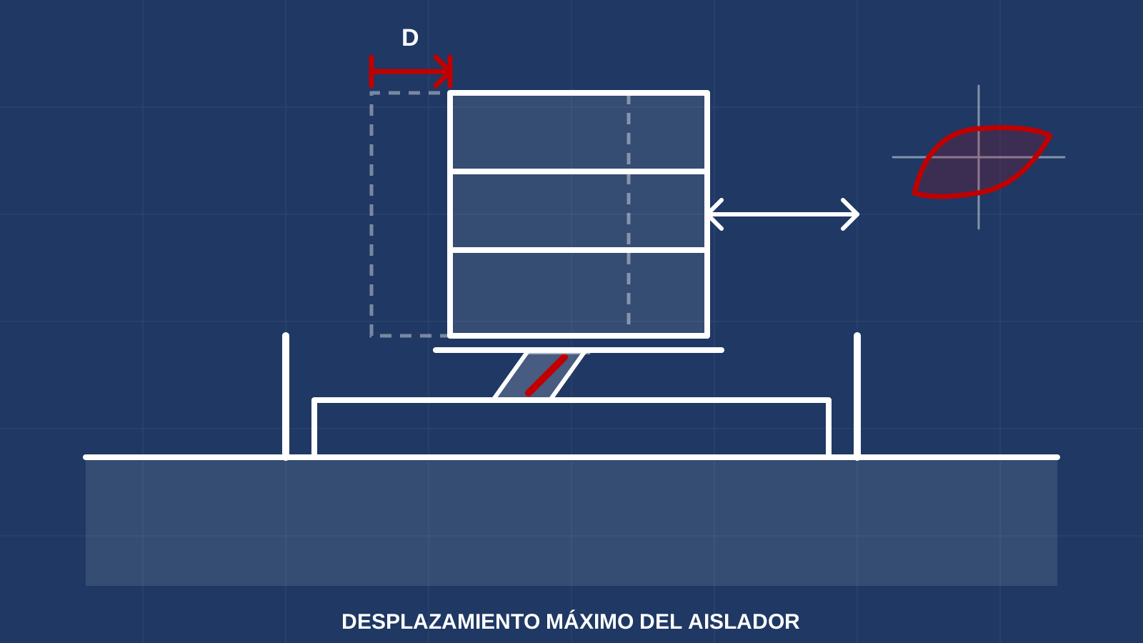
En un edificio aislado casi todo parte de un número: el desplazamiento máximo que alcanzarán los aisladores en el sismo de diseño. Con él se dimensiona el diámetro o el recorrido de cada dispositivo, se define el ancho del foso perimetral, se diseñan las conexiones flexibles de instalaciones y escaleras y se revisan las cargas en los aisladores. Equivocarse en este valor afecta a todo lo demás.
Qué es y por qué manda en el diseño
El aislador alarga el periodo de la estructura y, a cambio, concentra el movimiento en la capa de aislamiento: la superestructura se mueve poco, pero el aislador se desplaza decenas de centímetros. Ese recorrido, que se calcula para un sismo de diseño y para el sismo máximo considerado, es lo que el dispositivo debe poder soportar con estabilidad. Por eso aparece en la prueba de prototipo, en el foso y en la comparación entre sistemas (LRB, LDRB y FPS).
La fórmula básica (ASCE 7-22)
ASCE 7-22, capítulo 17, calcula el desplazamiento en el centro de rigidez a partir del espectro y del periodo y amortiguamiento efectivos del sistema:
- DM = g · SM1 · TM / (4π² · BM), para el sismo máximo considerado.
- DD = g · SD1 · TD / (4π² · BD), para el sismo de diseño.
Aquí SM1 y SD1 son las aceleraciones espectrales a 1 s, T es el periodo efectivo del sistema aislado y B es el coeficiente que reduce la demanda según el amortiguamiento efectivo. Mientras más largo el periodo y menor el amortiguamiento, más grande el desplazamiento. (Véase cómo leer un espectro de diseño.)
Del desplazamiento en el centro al desplazamiento total
El resultado anterior es el movimiento del centro de rigidez. Si el centro de masa no coincide con él (excentricidad real más accidental), el edificio también gira y las esquinas se desplazan más. ASCE 7 define un desplazamiento total DTD y DTM que incluye esa torsión y que tiene un valor mínimo respecto de DD y DM (revisa el valor exacto en la edición aplicable). La junta de separación del edificio debe dejar al menos el desplazamiento total máximo.
Qué factores lo mueven
- Sitio y espectro: a mayor SM1, mayor desplazamiento; los suelos blandos lo agravan (véase interacción suelo-estructura y zonificación sísmica).
- Periodo efectivo: alargarlo reduce fuerzas, pero aumenta el desplazamiento; hay que equilibrar ambos.
- Amortiguamiento: un aislador con núcleo de plomo (LRB) o con fricción disipa más energía y reduce D; un hule de bajo amortiguamiento (LDRB) se mueve más y se complementa con disipadores.
- Excentricidad y planta: plantas alargadas o con masa asimétrica elevan el desplazamiento en las esquinas.
- Cercanía a fallas: en sitios con pulsos de velocidad cercanos a la fuente puede haber demandas mayores que las del espectro; es un caso para estudio especial.
Qué define el desplazamiento en el proyecto
| Elemento | Qué se toma del desplazamiento |
|---|---|
| Aislador | Recorrido y estabilidad a DM (y verificación en prueba de prototipo) |
| Foso perimetral | Separación libre ≥ desplazamiento total máximo |
| Instalaciones y escaleras | Juntas y conexiones flexibles para ese recorrido |
| Cimentación y pedestales | Dimensiones de las placas y cargas con aisladores desplazados |
Errores comunes
- Diseñar sólo al sismo de diseño y olvidar el sismo máximo considerado para la capacidad del aislador y el foso.
- Dejar fuera la torsión y las esquinas del edificio.
- Usar propiedades nominales sin los límites superior e inferior por temperatura, envejecimiento y variabilidad; ASCE 7 pide revisar ambos.
- Foso obstruido en obra por rellenos, tuberías o jardineras (véase errores comunes de obra).
El desplazamiento que se calcula en la oficina es el que debe poder ocurrir en la obra. Por eso se verifica con las propiedades reales del dispositivo en las pruebas de producción y se revisa de nuevo en el mantenimiento.
En VELATOPH®
VELATOPH® fabrica en Manzanillo, Colima, aisladores elastoméricos LRB y LDRB, aisladores de péndulo FPS y DFP y disipadores DEF y DVF.
Si estás definiendo el desplazamiento de diseño de tu proyecto, te ofrecemos una evaluación técnica gratuita. Escríbenos por WhatsApp.
Fuentes
- ASCE/SEI 7-22, Minimum Design Loads and Associated Criteria for Buildings and Other Structures, capítulo 17 (estructuras con aislamiento sísmico), secciones 17.5 (desplazamientos y fuerzas) y 17.2.4 (separación).
- Naeim, F., Kelly, J. M. Design of Seismic Isolated Structures: From Theory to Practice. Wiley (1999).
- ISO 22762-1:2018, Elastomeric seismic-protection isolators — Test methods. iso.org
- FEMA P-751, NEHRP Recommended Provisions: Design Examples (ejemplos de diseño de estructuras aisladas). fema.gov
In an isolated building almost everything starts from one number: the maximum displacement the isolators will reach in the design earthquake. It sizes the diameter or travel of each device, sets the width of the perimeter moat, drives the flexible utility and stair connections and feeds the checks on isolator loads. An error in this value affects everything else.
What it is and why it governs the design
The isolator lengthens the structure’s period and, in exchange, concentrates the movement in the isolation layer: the superstructure moves little, but the isolator displaces tens of centimeters. That travel, calculated for a design earthquake and for the maximum considered earthquake, is what the device must withstand with stability. That is why it appears in the prototype test, in the moat and in the comparison between systems (LRB, LDRB and FPS).
The basic formula (ASCE 7-22)
ASCE 7-22, Chapter 17, computes the displacement at the center of rigidity from the spectrum and the effective period and damping of the system:
- DM = g · SM1 · TM / (4π² · BM), for the maximum considered earthquake.
- DD = g · SD1 · TD / (4π² · BD), for the design earthquake.
Here SM1 and SD1 are the 1-second spectral accelerations, T is the effective period of the isolated system and B is the coefficient that reduces the demand according to effective damping. The longer the period and the lower the damping, the larger the displacement. (See how to read a design spectrum.)
From center displacement to total displacement
The result above is the movement of the center of rigidity. If the center of mass does not coincide with it (actual plus accidental eccentricity), the building also rotates and the corners move farther. ASCE 7 defines a total displacement DTD and DTM that includes that torsion and has a minimum value relative to DD and DM (check the exact value in the applicable edition). The building’s separation joint must leave at least the maximum total displacement.
What moves it
- Site and spectrum: higher SM1 gives larger displacement; soft soils make it worse (see soil-structure interaction and seismic zoning).
- Effective period: lengthening it reduces forces but increases displacement; both must be balanced.
- Damping: a lead-core (LRB) or friction isolator dissipates more energy and reduces D; low-damping rubber (LDRB) moves more and is complemented with dampers.
- Eccentricity and plan shape: elongated plans or asymmetric mass raise the displacement at the corners.
- Near-fault sites: velocity pulses close to the source can produce demands above the spectrum; this calls for a special study.
What the displacement defines in the project
| Element | What is taken from the displacement |
|---|---|
| Isolator | Travel and stability at DM (and verification in the prototype test) |
| Perimeter moat | Clear separation ≥ maximum total displacement |
| Utilities and stairs | Flexible joints and connections for that travel |
| Foundation and pedestals | Plate dimensions and loads with displaced isolators |
Common mistakes
- Designing only for the design earthquake and forgetting the maximum considered earthquake for isolator capacity and moat.
- Leaving out torsion and the building corners.
- Using nominal properties without upper and lower bounds for temperature, aging and variability; ASCE 7 requires checking both.
- Obstructed moat on site because of fill, pipes or planters (see common site errors).
The displacement calculated in the office is the one that must be able to occur on site. That is why it is verified with the device’s actual properties in the production tests and checked again during maintenance.
At VELATOPH®
VELATOPH® manufactures in Manzanillo, Colima, LRB and LDRB elastomeric isolators, FPS and DFP pendulum isolators and DEF and DVF dissipators.
If you are defining the design displacement for your project, we offer a free technical assessment. Write to us on WhatsApp.
Sources
- ASCE/SEI 7-22, Minimum Design Loads and Associated Criteria for Buildings and Other Structures, Chapter 17 (seismically isolated structures), Sections 17.5 (displacements and forces) and 17.2.4 (separation).
- Naeim, F., Kelly, J. M. Design of Seismic Isolated Structures: From Theory to Practice. Wiley (1999).
- ISO 22762-1:2018, Elastomeric seismic-protection isolators — Test methods. iso.org
- FEMA P-751, NEHRP Recommended Provisions: Design Examples (design examples of isolated structures). fema.gov