Un edificio que se mueve durante un sismo almacena energía en sus columnas y trabes, y la libera vibrando. Si esa energía no se disipa, la estructura la absorbe dañándose. Los disipadores de fluido viscoso (DVF) atacan el problema de frente: convierten el movimiento en calor dentro de un cilindro lleno de fluido, igual que el amortiguador de un automóvil, pero a la escala de un edificio o un puente. En este artículo explicamos cómo trabajan, cómo se dimensionan y en qué estructuras dan mejor resultado.
Cómo funciona un DVF
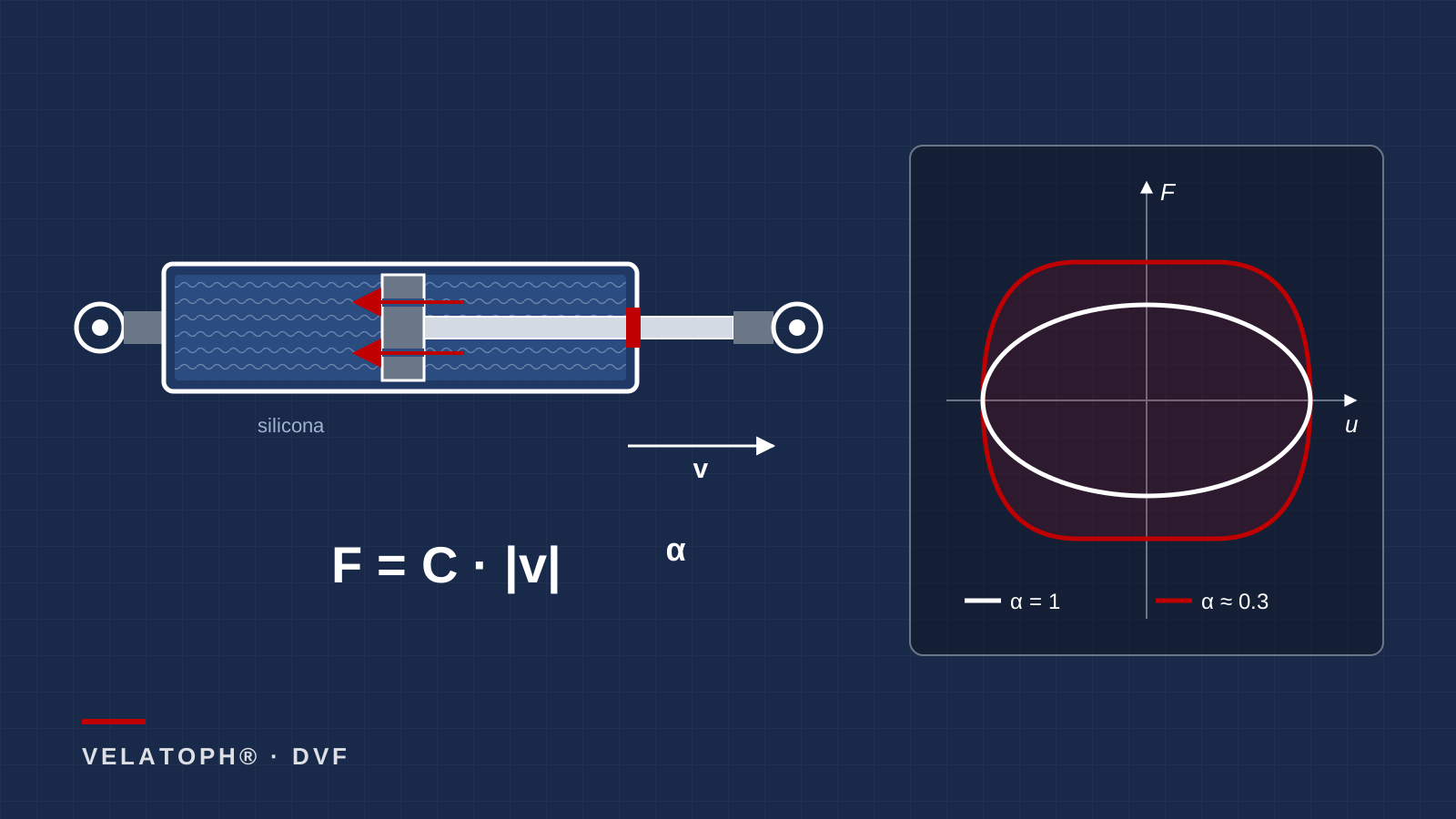
Un DVF es un cilindro de acero lleno de un fluido de silicona, con un pistón que lo divide en dos cámaras. La cabeza del pistón tiene orificios calibrados. Cuando la estructura se deforma, el vástago empuja el pistón y obliga al fluido a pasar a alta velocidad de una cámara a otra. La resistencia a ese flujo genera la fuerza del disipador, y la energía se transforma en calor.
La fuerza depende de la velocidad relativa entre los extremos del dispositivo, no del desplazamiento. Se describe con una ley potencial:
F = C · |v|α · signo(v)
donde C es la constante de amortiguamiento y α el exponente de velocidad. En ingeniería sísmica se usan valores de α entre 0.3 y 1.0 (Symans et al., 2008). Con α = 1 el disipador es lineal: la fuerza crece en proporción directa a la velocidad. Con α menor que 1 es no lineal: la fuerza crece rápido a velocidades bajas y luego se aplana, lo que limita la carga que llega a las conexiones durante un sismo intenso.
La ventaja clave: la fuerza llega fuera de fase
En un ciclo de vibración, la velocidad es máxima cuando el edificio pasa por su posición de reposo y es cero en el desplazamiento máximo. Por eso la fuerza del DVF es máxima justo cuando los esfuerzos elásticos de las columnas son mínimos, y casi nula cuando éstos son máximos. En un disipador lineal sometido a movimiento armónico el ciclo fuerza-desplazamiento es una elipse perfecta.
Esta propiedad distingue al DVF de otros dispositivos: reduce desplazamientos y derivas sin sumar, en el instante más crítico, una fuerza adicional a la que ya soportan las columnas y la cimentación. Además, el DVF prácticamente no agrega rigidez, de modo que no acorta el periodo de la estructura ni la hace atraer más aceleración.
Cómo se dimensiona: paso a paso
El dimensionamiento parte de una idea sencilla: el DVF agrega amortiguamiento, y más amortiguamiento significa menor respuesta espectral. Un proceso típico es:
- 1. Fijar el objetivo de desempeño. Deriva máxima por nivel, aceleración de piso o desplazamiento del sistema de aislamiento que se quiere alcanzar.
- 2. Estimar el amortiguamiento necesario. Con el espectro de diseño del sitio se calcula cuánto amortiguamiento total hace falta para llegar a ese objetivo.
- 3. Repartir los disipadores. Se colocan donde la velocidad relativa entre niveles es mayor, por lo general en los entrepisos con más deriva, y de forma simétrica para no inducir torsión.
- 4. Calcular C y elegir α. Para un disipador lineal en un sistema de un grado de libertad, la energía disipada por ciclo es WD = π·C·ω·u0² y el amortiguamiento equivalente es ξ = WD / (4π·ES), donde ES es la energía elástica máxima. Para disipadores no lineales, FEMA 450 tabula un factor λ en función de α (λ = π para α = 1).
- 5. Verificar con análisis no lineal. Se revisa la respuesta con registros sísmicos y con límites superior e inferior de las propiedades del dispositivo.
- 6. Diseñar contravientos y conexiones para la fuerza máxima del disipador a la velocidad máxima esperada.
El efecto del exponente α, en números
Un cálculo ilustrativo, no de un proyecto real: si la velocidad del disipador se duplica, la fuerza se multiplica por 2α.
| Exponente α | Si la velocidad se duplica, la fuerza… | Forma del ciclo |
|---|---|---|
| 1.0 (lineal) | se duplica (×2.00) | Elipse |
| 0.5 | sube 41 % (×1.41) | Intermedia |
| 0.3 | sube 23 % (×1.23) | Casi rectangular |
Un α bajo controla la fuerza máxima en sismos que superan el de diseño y disipa más energía por ciclo con la misma fuerza máxima. Un α igual a 1 simplifica el análisis, porque el disipador puede modelarse como un amortiguador lineal. La elección se hace con el análisis, no por costumbre.
Dónde rinden más
- Edificios flexibles y altos: marcos de acero o de concreto con derivas grandes, donde la velocidad entre niveles es alta y el disipador trabaja a plena capacidad.
- Puentes y estructuras esbeltas: controlan el movimiento longitudinal del tablero y las vibraciones de torres.
- Combinados con aislamiento sísmico: en la interfaz de aislamiento reducen el desplazamiento de los aisladores y el tamaño de la junta perimetral. Conviene revisar las aceleraciones de piso, porque demasiado amortiguamiento puede aumentar la respuesta en modos superiores.
- Reforzamiento de edificios existentes: se instalan en contravientos dentro de los marcos y reducen las derivas sin aumentar mucho la rigidez ni la carga a la cimentación.
- Edificios donde el contenido importa: al reducir derivas y aceleraciones protegen acabados, instalaciones y equipos.
Rinden menos en estructuras muy rígidas, como edificios bajos de muros de concreto, donde los desplazamientos y las velocidades entre niveles son pequeños y el disipador casi no trabaja.
Errores comunes de diseño y obra
- Contravientos flexibles: si el contraviento que sostiene al disipador se deforma mucho, el DVF recibe menos velocidad y disipa menos de lo calculado.
- Holguras en las conexiones: pernos con juego o articulaciones flojas retrasan la entrada en acción del disipador en sismos pequeños.
- Carrera insuficiente: el pistón debe tener recorrido para el desplazamiento máximo esperado más un margen; un tope a media carrera transmite impactos a la estructura.
- Inspección olvidada: hay que revisar periódicamente fugas de fluido, sellos y corrosión del vástago.
En VELATOPH®
VELATOPH® fabrica en Manzanillo, Colima, el disipador de fluido viscoso (DVF), un amortiguador de pistón para controlar velocidades y aceleraciones en puentes, torres y estructuras esbeltas. También fabrica el disipador por fricción (DEF) y aisladores sísmicos elastoméricos y de péndulo. En Santiago de los Caballeros, República Dominicana, se instalaron 37 disipadores DVF entre 2023 y 2024.
Si tienes un edificio nuevo o existente y quieres saber si los disipadores viscosos pueden reducir sus derivas o el tamaño de su sistema de aislamiento, te ofrecemos una evaluación técnica gratuita. Escríbenos por WhatsApp.
Fuentes
- Constantinou, M. C. y Symans, M. D. (1992). Experimental and Analytical Investigation of Seismic Response of Structures with Supplemental Fluid Viscous Dampers. Reporte técnico NCEER-92-0032. buffalo.edu/mceer
- Symans, M. D. et al. (2008). "Energy dissipation systems for seismic applications: current practice and recent developments". Journal of Structural Engineering, 134(1), 3–21. doi.org/10.1061/(ASCE)0733-9445(2008)134:1(3)
- Taylor Devices. Practical Design Procedure for Steel Moment Frames with Fluid Viscous Dampers (documento técnico 116). taylordevices.com
- FEMA 450 (2003). NEHRP Recommended Provisions for Seismic Regulations for New Buildings and Other Structures, capítulo 15 (estructuras con sistemas de amortiguamiento). nehrp.gov
- ASCE/SEI 7-22, Minimum Design Loads and Associated Criteria for Buildings and Other Structures, capítulo 18. asce.org
A building that moves during an earthquake stores energy in its columns and beams and releases it by vibrating. If that energy is not dissipated, the structure absorbs it by being damaged. Fluid viscous dampers (FVD) tackle the problem head-on: they turn motion into heat inside a fluid-filled cylinder, just like a car's shock absorber, but at the scale of a building or a bridge. In this article we explain how they work, how they are sized and in which structures they perform best.
How an FVD works
An FVD is a steel cylinder filled with silicone fluid, with a piston that divides it into two chambers. The piston head has calibrated orifices. When the structure deforms, the rod pushes the piston and forces the fluid to flow at high speed from one chamber to the other. The resistance to that flow generates the damper force, and the energy is turned into heat.
The force depends on the relative velocity between the ends of the device, not on displacement. It is described by a power law:
F = C · |v|α · sign(v)
where C is the damping constant and α the velocity exponent. In earthquake engineering, α values between 0.3 and 1.0 are used (Symans et al., 2008). With α = 1 the damper is linear: the force grows in direct proportion to velocity. With α below 1 it is nonlinear: the force rises quickly at low velocities and then flattens out, which limits the load reaching the connections during a strong earthquake.
The key advantage: the force arrives out of phase
In a vibration cycle, velocity is greatest when the building passes through its rest position and is zero at maximum displacement. That is why the FVD force is greatest exactly when the elastic stresses in the columns are smallest, and almost zero when those are greatest. In a linear damper under harmonic motion, the force-displacement loop is a perfect ellipse.
This property sets the FVD apart from other devices: it reduces displacements and drifts without adding, at the most critical instant, extra force to what the columns and foundation already carry. In addition, the FVD adds practically no stiffness, so it does not shorten the period of the structure or make it attract more acceleration.
How it is sized: step by step
Sizing starts from a simple idea: the FVD adds damping, and more damping means a lower spectral response. A typical process is:
- 1. Set the performance target. Maximum story drift, floor acceleration or isolation system displacement to be achieved.
- 2. Estimate the required damping. Using the site design spectrum, the total damping needed to reach that target is calculated.
- 3. Distribute the dampers. They are placed where the relative velocity between floors is highest, usually in the stories with the most drift, and symmetrically so as not to induce torsion.
- 4. Calculate C and choose α. For a linear damper in a single-degree-of-freedom system, the energy dissipated per cycle is WD = π·C·ω·u0² and the equivalent damping is ξ = WD / (4π·ES), where ES is the maximum elastic energy. For nonlinear dampers, FEMA 450 tabulates a factor λ as a function of α (λ = π for α = 1).
- 5. Verify with nonlinear analysis. The response is checked with earthquake records and with upper and lower bounds of the device properties.
- 6. Design braces and connections for the maximum damper force at the maximum expected velocity.
The effect of the exponent α, in numbers
An illustrative calculation, not from a real project: if the damper velocity doubles, the force is multiplied by 2α.
| Exponent α | If velocity doubles, the force… | Loop shape |
|---|---|---|
| 1.0 (linear) | doubles (×2.00) | Ellipse |
| 0.5 | rises 41% (×1.41) | Intermediate |
| 0.3 | rises 23% (×1.23) | Nearly rectangular |
A low α controls the maximum force in earthquakes that exceed the design event and dissipates more energy per cycle for the same maximum force. An α equal to 1 simplifies the analysis, because the damper can be modeled as a linear dashpot. The choice is made with analysis, not by habit.
Where they perform best
- Flexible and tall buildings: steel or concrete frames with large drifts, where the velocity between floors is high and the damper works at full capacity.
- Bridges and slender structures: they control longitudinal deck motion and tower vibrations.
- Combined with seismic isolation: at the isolation interface they reduce isolator displacement and the size of the perimeter gap. Floor accelerations should be checked, because too much damping can increase the response in higher modes.
- Retrofit of existing buildings: they are installed in braces within the frames and reduce drifts without greatly increasing stiffness or foundation loads.
- Buildings where contents matter: by reducing drifts and accelerations they protect finishes, utilities and equipment.
They perform less well in very stiff structures, such as low-rise concrete wall buildings, where displacements and velocities between floors are small and the damper barely works.
Common design and construction mistakes
- Flexible braces: if the brace supporting the damper deforms a lot, the FVD receives less velocity and dissipates less than calculated.
- Slack in the connections: bolts with play or loose joints delay the damper's engagement in small earthquakes.
- Insufficient stroke: the piston must have travel for the maximum expected displacement plus a margin; bottoming out mid-event transmits impacts to the structure.
- Forgotten inspection: fluid leaks, seals and rod corrosion must be checked periodically.
At VELATOPH®
VELATOPH® manufactures in Manzanillo, Colima, the fluid viscous damper (DVF), a piston damper to control velocities and accelerations in bridges, towers and slender structures. It also manufactures the friction damper (DEF) and elastomeric and pendulum seismic isolators. In Santiago de los Caballeros, Dominican Republic, 37 DVF dampers were installed between 2023 and 2024.
If you have a new or existing building and want to know whether viscous dampers can reduce its drifts or the size of its isolation system, we offer a free technical assessment. Write to us on WhatsApp.
Sources
- Constantinou, M. C. and Symans, M. D. (1992). Experimental and Analytical Investigation of Seismic Response of Structures with Supplemental Fluid Viscous Dampers. Technical report NCEER-92-0032. buffalo.edu/mceer
- Symans, M. D. et al. (2008). "Energy dissipation systems for seismic applications: current practice and recent developments". Journal of Structural Engineering, 134(1), 3–21. doi.org/10.1061/(ASCE)0733-9445(2008)134:1(3)
- Taylor Devices. Practical Design Procedure for Steel Moment Frames with Fluid Viscous Dampers (technical paper 116). taylordevices.com
- FEMA 450 (2003). NEHRP Recommended Provisions for Seismic Regulations for New Buildings and Other Structures, Chapter 15 (structures with damping systems). nehrp.gov
- ASCE/SEI 7-22, Minimum Design Loads and Associated Criteria for Buildings and Other Structures, Chapter 18. asce.org