Casi todo el diseño sísmico de un edificio sale de una sola gráfica: el espectro de diseño. Ahí se lee qué aceleración debe resistir la estructura, cuánto se va a desplazar y por qué dos edificios en el mismo terreno pueden recibir sismos muy distintos. Si entiendes cómo se lee esa curva, entiendes también por qué el aislamiento sísmico funciona: lo que hace un aislador es mover el edificio a otra zona del espectro. En este artículo la explicamos paso a paso, sin más matemáticas de las necesarias.
Qué es un espectro de respuesta
Imagina una fila de péndulos invertidos, cada uno con distinta rigidez: unos cortos y tiesos, otros largos y flexibles. Cada uno representa un edificio simplificado con un solo modo de vibrar, caracterizado por su periodo natural T: el tiempo, en segundos, que tarda en ir y volver una vez. Si sometemos toda la fila al mismo registro sísmico y anotamos la aceleración máxima que alcanza cada péndulo, obtenemos una curva: el espectro de respuesta de ese sismo.
Un espectro de respuesta describe un sismo en particular. El espectro de diseño, en cambio, es una curva suavizada que fija la norma para un sitio, a partir del peligro sísmico de la región y del tipo de suelo. No es un sismo real: es la envolvente de los sismos que se esperan en ese lugar, con un nivel de probabilidad acordado.
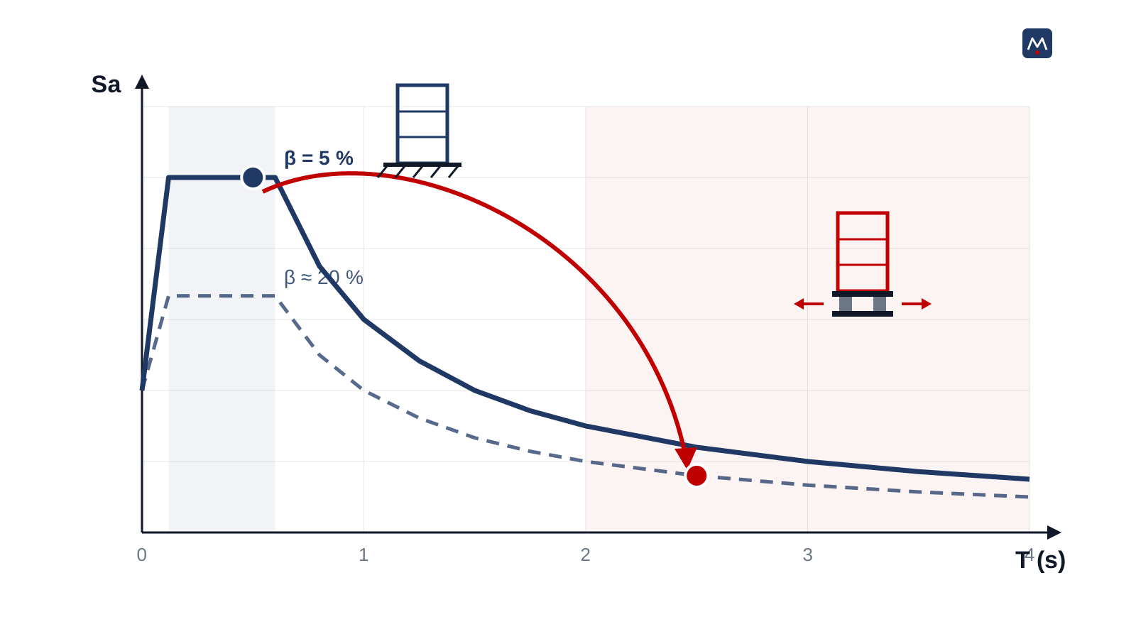
Las zonas del espectro de ASCE 7
En su forma clásica de dos parámetros (ASCE 7, sección 11.4), el espectro se construye con dos valores del sitio: SDS, la aceleración de diseño en periodos cortos, y SD1, la aceleración de diseño a 1 segundo. Con ellos se definen tres periodos de transición, T0 = 0.2·SD1/SDS, TS = SD1/SDS y TL (periodo largo, dado por mapas), y cuatro tramos:
| Tramo | Periodo | Aceleración Sa | Qué estructuras caen ahí |
|---|---|---|---|
| Rampa | T < T0 | Sube de 0.4·SDS a SDS | Muy rígidas: muros cortos, equipos anclados |
| Meseta | T0 a TS | Constante = SDS (el máximo) | Edificios bajos y medianos de base fija |
| Rama descendente | TS a TL | SD1/T: baja al alargar el periodo | Edificios altos y estructuras aisladas |
| Periodo largo | T > TL | SD1·TL/T² | Rascacielos y puentes muy flexibles |
Para ubicar un edificio en la gráfica hace falta su periodo. Como primera estimación, ASCE 7 permite tomar T ≈ 0.1·N para marcos resistentes a momento de hasta 12 niveles, donde N es el número de pisos (ecuación 12.8-8). Un edificio de cinco niveles ronda 0.5 s: cae de lleno en la meseta, la zona de mayor aceleración.
Un matiz importante: ASCE 7-22 introdujo el espectro multiperiodo, con ordenadas en 22 periodos de 0 a 10 s tomadas de la base de datos del USGS, para sitios en Estados Unidos. Fuera de ese país, donde esa base no existe, se sigue usando el espectro de dos parámetros (Ghosh, 2025). En México, además, el espectro lo definen las normas locales: las NTC para Diseño por Sismo en la Ciudad de México y el Manual de Diseño de Obras Civiles de CFE (Diseño por Sismo, 2015) en el resto del país, cada uno con su propio procedimiento.
El papel del amortiguamiento
El espectro de diseño estándar se calcula para un amortiguamiento del 5 %, un valor típico de estructuras de concreto o acero en el rango elástico. El amortiguamiento es la capacidad de la estructura de disipar energía en cada ciclo; mientras más disipa, menor es su respuesta máxima. Por eso, para sistemas con amortiguamiento mayor, el capítulo 17 de ASCE 7 divide la respuesta entre un coeficiente BM (tabla 17.5-1):
- Amortiguamiento efectivo ≤ 2 %: BM = 0.8 (la respuesta crece).
- 5 %: BM = 1.0 (espectro base).
- 10 %: BM = 1.2.
- 20 %: BM = 1.5.
- 30 %: BM = 1.7; 40 %: BM = 1.9; 50 % o más: BM = 2.0 (tope).
Los aisladores con núcleo de plomo (LRB) y los de péndulo de fricción (FPS, DFP) disipan energía en cada ciclo de histéresis, y es habitual que el sistema de aislamiento alcance amortiguamientos efectivos del orden de 15 a 30 %. Ese amortiguamiento se calcula para cada proyecto a partir de las pruebas del dispositivo; no es un valor que se suponga.
Por qué aislar “alarga” el periodo
El periodo de una estructura depende de su masa y de su rigidez: T = 2π·√(m/K). Un aislador no cambia la masa del edificio, pero coloca debajo de él una capa con rigidez lateral muy baja. El sistema completo se vuelve mucho más flexible y su periodo pasa de décimas de segundo a dos, tres o más segundos. En el espectro, eso equivale a mover el edificio de la meseta a la rama descendente, y además a una curva de mayor amortiguamiento.
Con los valores ilustrativos de la figura (SDS = 1.0 g y SD1 = 0.6 g; no corresponden a ningún sitio ni proyecto real):
La aceleración espectral baja a una sexta parte. Como las fuerzas sísmicas son masa por aceleración, la superestructura puede diseñarse para fuerzas mucho menores y, sobre todo, sus pisos y contenidos reciben mucho menos movimiento.
El precio: el desplazamiento
Lo que el espectro de aceleraciones regala, el de desplazamientos lo cobra. El desplazamiento espectral crece con el periodo: Sd = Sa·g·T²/(4π²). Por eso ASCE 7-22 calcula el desplazamiento máximo del sistema de aislamiento con el sismo máximo considerado (MCER) mediante DM = g·SM1·TM/(4π²·BM) (ecuación 17.5-1).
En el ejemplo, con SM1 = 1.5·SD1 = 0.9 g, TM = 2.5 s y BM = 1.5, resulta DM ≈ 0.37 m. Casi 40 centímetros que el edificio debe poder moverse respecto al terreno, sin chocar con nada. De ahí salen el foso perimetral, las conexiones flexibles de instalaciones y el tamaño de cada aislador. Por eso decimos que el desplazamiento define el diseño: más amortiguamiento lo reduce, pero un periodo más largo lo aumenta.
Cómo leer el espectro de tu proyecto
- Identifica qué norma rige el sitio y de dónde sale el espectro (NTC-CDMX, CFE-Sismo, ASCE 7 o un estudio de sitio).
- Ubica el periodo fundamental del edificio con base fija y anota en qué tramo cae.
- Revisa dónde termina la meseta (TS) y cuánto baja la curva entre 2 y 4 s: ésa es la ganancia potencial del aislamiento.
- Busca picos en periodos largos: son la señal de un suelo blando que hay que estudiar con cuidado.
- Calcula el desplazamiento del sistema aislado con el sismo máximo, no con el de diseño, antes de comprometer el foso y la arquitectura.
- Usa el amortiguamiento que respalden las pruebas de los aisladores, con sus límites superior e inferior de propiedades.
En VELATOPH®
VELATOPH® fabrica en Manzanillo, Colima, aisladores elastoméricos LRB y LDRB, aisladores de péndulo FPS y DFP y disipadores DEF y DVF, y trabaja con la normativa ASCE 7-22 (capítulos 17 y 18), AASHTO LRFD, ISO 22762, NTC-CDMX 2023 y CFE-Sismo 2015.
Si tienes el espectro de tu proyecto y quieres saber cuánto podría reducir el aislamiento las fuerzas y qué desplazamiento implica, te ofrecemos una evaluación técnica gratuita. Escríbenos por WhatsApp.
Fuentes
- ASCE/SEI 7-22, Minimum Design Loads and Associated Criteria for Buildings and Other Structures, capítulos 11, 12 y 17 (secciones 11.4, 12.8 y 17.5). asce.org
- ASCE. ASCE Hazard Tool (parámetros sísmicos y espectro multiperiodo del USGS). ascehazardtool.org
- Ghosh, S. K. (2025). Is Continued Use of the Two-Period Design Spectrum in the Equivalent Lateral Force Procedure of Seismic Design Permitted by ASCE 7-22? ICC Building Safety Journal. iccsafe.org
- FEMA (2010). Earthquake-Resistant Design Concepts: An Introduction to the NEHRP Recommended Seismic Provisions (FEMA P-749). fema.gov
- PCI Journal (1986). Performance of Precast and Prestressed Concrete in Mexico Earthquake. pci.org
- EGU Blogs (2015). The Mexico City earthquake, 19 September 1985. blogs.egu.eu
Almost all of a building's seismic design comes from a single graph: the design spectrum. It tells you what acceleration the structure must resist, how far it will move and why two buildings on the same site can experience very different earthquakes. If you understand how to read that curve, you also understand why seismic isolation works: what an isolator does is move the building to another zone of the spectrum. In this article we explain it step by step, with no more math than necessary.
What a response spectrum is
Imagine a row of inverted pendulums, each with a different stiffness: some short and stiff, others tall and flexible. Each one represents a simplified building with a single vibration mode, characterized by its natural period T: the time, in seconds, it takes to swing back and forth once. If we subject the whole row to the same earthquake record and note the peak acceleration each pendulum reaches, we obtain a curve: the response spectrum of that earthquake.
A response spectrum describes one particular earthquake. The design spectrum, by contrast, is a smoothed curve set by the code for a site, based on the region's seismic hazard and the soil type. It is not a real earthquake: it is the envelope of the earthquakes expected at that location, at an agreed probability level.
The zones of the ASCE 7 spectrum
In its classic two-parameter form (ASCE 7, Section 11.4), the spectrum is built from two site values: SDS, the short-period design acceleration, and SD1, the design acceleration at 1 second. They define three transition periods, T0 = 0.2·SD1/SDS, TS = SD1/SDS and TL (long period, given by maps), and four segments:
| Segment | Period | Acceleration Sa | Which structures fall there |
|---|---|---|---|
| Ramp | T < T0 | Rises from 0.4·SDS to SDS | Very stiff: short walls, anchored equipment |
| Plateau | T0 to TS | Constant = SDS (the maximum) | Low- and mid-rise fixed-base buildings |
| Descending branch | TS to TL | SD1/T: drops as the period lengthens | Tall buildings and isolated structures |
| Long period | T > TL | SD1·TL/T² | Skyscrapers and very flexible bridges |
To place a building on the graph you need its period. As a first estimate, ASCE 7 allows T ≈ 0.1·N for moment-resisting frames up to 12 stories, where N is the number of stories (Equation 12.8-8). A five-story building is around 0.5 s: it falls squarely on the plateau, the zone of highest acceleration.
An important nuance: ASCE 7-22 introduced the multi-period spectrum, with ordinates at 22 periods from 0 to 10 s taken from the USGS database, for sites in the United States. Outside that country, where that database does not exist, the two-parameter spectrum is still used (Ghosh, 2025). In Mexico, moreover, the spectrum is defined by local standards: the NTC for Seismic Design in Mexico City and the CFE Civil Works Design Manual (Seismic Design, 2015) in the rest of the country, each with its own procedure.
The role of damping
The standard design spectrum is computed for 5% damping, a typical value for concrete or steel structures in the elastic range. Damping is a structure's ability to dissipate energy in each cycle; the more it dissipates, the lower its peak response. That is why, for systems with higher damping, Chapter 17 of ASCE 7 divides the response by a coefficient BM (Table 17.5-1):
- Effective damping ≤ 2%: BM = 0.8 (the response increases).
- 5%: BM = 1.0 (base spectrum).
- 10%: BM = 1.2.
- 20%: BM = 1.5.
- 30%: BM = 1.7; 40%: BM = 1.9; 50% or more: BM = 2.0 (cap).
Lead rubber bearings (LRB) and friction pendulum isolators (FPS, DFP) dissipate energy in every hysteresis cycle, and it is common for the isolation system to reach effective damping on the order of 15 to 30%. That damping is computed for each project from the device tests; it is not a value to be assumed.
Why isolation “lengthens” the period
A structure's period depends on its mass and stiffness: T = 2π·√(m/K). An isolator does not change the building's mass, but it places beneath it a layer with very low lateral stiffness. The whole system becomes much more flexible and its period goes from tenths of a second to two, three or more seconds. On the spectrum, this amounts to moving the building from the plateau to the descending branch, and also onto a higher-damping curve.
With the illustrative values in the figure (SDS = 1.0 g and SD1 = 0.6 g; they do not correspond to any real site or project):
The spectral acceleration drops to one sixth. Since seismic forces are mass times acceleration, the superstructure can be designed for much lower forces and, above all, its floors and contents receive much less motion.
The price: displacement
What the acceleration spectrum gives, the displacement spectrum takes back. Spectral displacement grows with the period: Sd = Sa·g·T²/(4π²). That is why ASCE 7-22 computes the maximum displacement of the isolation system under the maximum considered earthquake (MCER) with DM = g·SM1·TM/(4π²·BM) (Equation 17.5-1).
In the example, with SM1 = 1.5·SD1 = 0.9 g, TM = 2.5 s and BM = 1.5, the result is DM ≈ 0.37 m. Almost 40 centimeters that the building must be able to move relative to the ground without hitting anything. That drives the perimeter moat, the flexible utility connections and the size of each isolator. This is why we say displacement defines the design: more damping reduces it, but a longer period increases it.
How to read your project's spectrum
- Identify which code governs the site and where the spectrum comes from (NTC-CDMX, CFE-Sismo, ASCE 7 or a site-specific study).
- Locate the building's fixed-base fundamental period and note which segment it falls in.
- Check where the plateau ends (TS) and how much the curve drops between 2 and 4 s: that is the potential gain from isolation.
- Look for peaks at long periods: they signal a soft soil that must be studied carefully.
- Compute the isolated system's displacement under the maximum earthquake, not the design earthquake, before committing to the moat and the architecture.
- Use the damping supported by the isolator tests, with its upper- and lower-bound properties.
At VELATOPH®
VELATOPH® manufactures in Manzanillo, Colima, LRB and LDRB elastomeric isolators, FPS and DFP pendulum isolators and DEF and DVF dampers, and works with the ASCE 7-22 (Chapters 17 and 18), AASHTO LRFD, ISO 22762, NTC-CDMX 2023 and CFE-Sismo 2015 standards.
If you have your project's spectrum and want to know how much isolation could reduce the forces and what displacement it implies, we offer a free technical assessment. Write to us on WhatsApp.
Sources
- ASCE/SEI 7-22, Minimum Design Loads and Associated Criteria for Buildings and Other Structures, Chapters 11, 12 and 17 (Sections 11.4, 12.8 and 17.5). asce.org
- ASCE. ASCE Hazard Tool (seismic parameters and USGS multi-period spectrum). ascehazardtool.org
- Ghosh, S. K. (2025). Is Continued Use of the Two-Period Design Spectrum in the Equivalent Lateral Force Procedure of Seismic Design Permitted by ASCE 7-22? ICC Building Safety Journal. iccsafe.org
- FEMA (2010). Earthquake-Resistant Design Concepts: An Introduction to the NEHRP Recommended Seismic Provisions (FEMA P-749). fema.gov
- PCI Journal (1986). Performance of Precast and Prestressed Concrete in Mexico Earthquake. pci.org
- EGU Blogs (2015). The Mexico City earthquake, 19 September 1985. blogs.egu.eu